
Thrust/torque measuring device for pod test

A torque measurement and thrust technology, applied in the direction of measuring devices, force/torque/power measuring instruments, instruments, etc., can solve the problems that the size of the device cannot meet the standard required by the test, consume a lot of manpower and material resources, research misleading effects, etc., and achieve prediction and optimized performance, convenient and concise layout, and high measurement accuracy

Active Publication Date: 2015-05-20
HARBIN ENG UNIV
View PDF6 Cites 18 Cited by
  • Summary
  • Abstract
  • Description
  • Claims
  • Application Information

AI Technical Summary

Problems solved by technology

As far as the current research is concerned, most of the new design concepts are still in the stage of theoretical and numerical research. The main reason for this phenomenon is that it takes a lot of manpower and material resources to conduct experimental research and actual ship research, and requires sophisticated testing devices. In particular, the absence of a stable built-in measuring device for precise and reliable measurements of test thrust and torque
The disadvantages of using theoretical research methods are also obvious. Due to the differences in the selected models and control equations, the research results may be very different from the actual situation, and it is easy to mislead further research.
However, the size of the sensor or self-propelled instrument required by the experiment should be small enough and the precision should be high enough. At present, the structure of the existing sensor or self-propelled instrument is heavier than the structure of the thrust torque sensor required by the test. , resulting in measurement accuracy, stability, especially the size of the device cannot meet the standard required by the test

Method used


Image

  • Thrust/torque measuring device for pod test
  • Thrust/torque measuring device for pod test
  • Thrust/torque measuring device for pod test

Examples


Embodiment Construction

[0009] The present invention will be further described in detail below in conjunction with the accompanying drawings and specific embodiments.

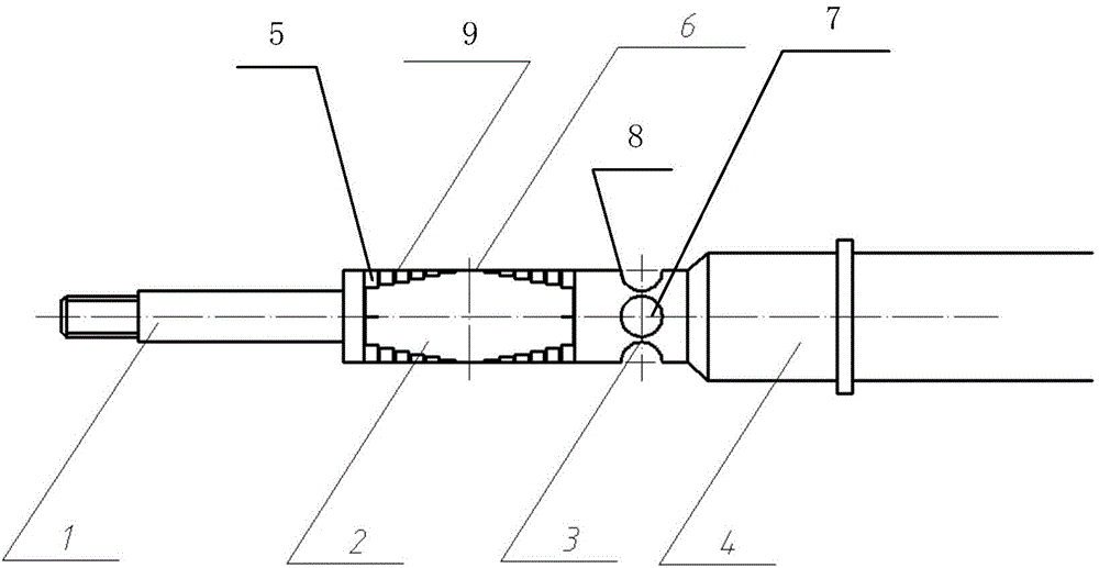
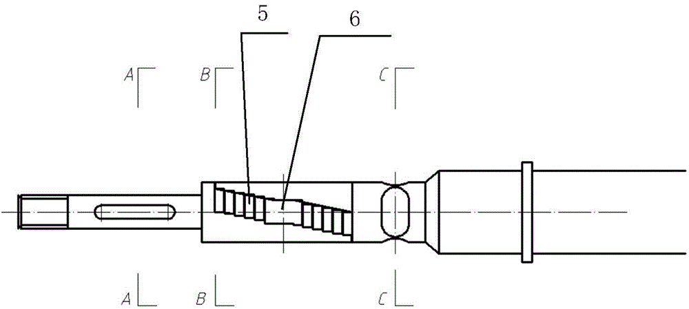
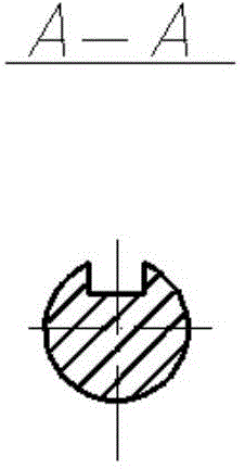
[0010] to combine Figure 1 to Figure 3(C) , the present invention includes a built-in motor in the cabin, a main shaft 4 connected to the output shaft of the built-in motor in the cabin, a thrust torque sensor connected to the main shaft 4, a propeller installation shaft 1 connected with the thrust torque sensor, and a set on the propeller installation shaft 1 The propeller, the thrust torque sensor includes a torque measurement section 3 and a thrust measurement section 2, the center of the torque measurement section 3 is provided with an opening 7, and the first full-bridge strain gauge is pasted in the opening 7, and in the opening 7 Semicircular grooves 8 are symmetrically arranged on both sides, and the middle position of the thrust measuring section 2 is pasted with a second full-bridge strain gauge 6, and a row of through hole...


PUM


Abstract

The invention provides a thrust / torque measuring device for a pod test. The thrust / torque measuring device comprises a main shaft, wherein one end of the main shaft is directly connected with an internal motor of a cabin, and the other end of the main shaft is connected with a thrust / torque sensor; the thrust / torque sensor is divided into a thrust measuring section and a torque measuring section and is connected with a propeller mounting shaft; a propeller is directly mounted on the propeller mounting shaft; thrust and torque generated by the propeller are directly measured by the thrust / torque sensor. The thrust / torque measuring device is simple in structure; the thrust / torque sensor can be mounted by abutting against the propeller; the device is small and compact in form, can be conveniently arranged in the cabin for use, and is high in measurement accuracy; the interference of two component forces is small; the measurement error of measuring the thrust and the torque by a conventional self-propulsion instrument caused by shaft system friction is eliminated, and the device plays an important role in deep research on the experiment of a pod propeller.

Description

technical field [0001] The invention relates to a thrust torque measuring device, in particular to a thrust torque measuring device for a pod test. Background technique [0002] With the development of electric propulsion technology, pod propulsion is gradually being adopted all over the world as a typical representative with its superior hydrodynamic performance and reliable installation and use process. Various types of pod propellers have been gradually developed by people. In order to put the new pod propellers into use as soon as possible, it is necessary to study their hydrodynamic performance in detail. As far as the current research is concerned, most of the new design concepts are still in the stage of theoretical and numerical research. The main reason for this phenomenon is that it takes a lot of manpower and material resources to conduct experimental research and actual ship research, and requires sophisticated testing devices. In particular, there is a lack of ...

Claims


Application Information

Patent Timeline
IPC IPC(8): G01L5/00
Inventor 郭春雨豆鹏飞景涛赵大刚
Owner HARBIN ENG UNIV
Learn More