
Compression fixture on mechanical tensile creep tester

A tensile creep and testing machine technology, applied in the field of material mechanics research, can solve problems such as the limitation of the action direction of the creep loading range, and achieve the effects of high machining accuracy, guaranteed accuracy and simple structure

Inactive Publication Date: 2015-05-20
NANJING UNIV OF SCI & TECH
View PDF7 Cites 4 Cited by
  • Summary
  • Abstract
  • Description
  • Claims
  • Application Information

AI Technical Summary

Problems solved by technology

Although the technology of mechanical creep test equipment has been developed and mature, its creep loading range is limited by the direction of force, and only tensile creep tests can be performed.

Method used


Image

  • Compression fixture on mechanical tensile creep tester
  • Compression fixture on mechanical tensile creep tester

Examples


Embodiment

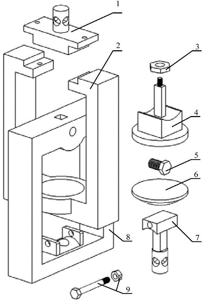
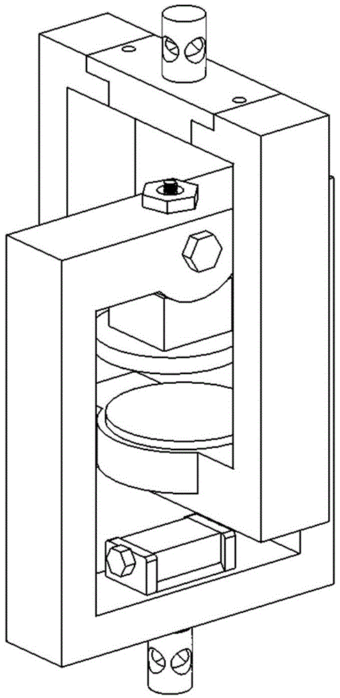
[0022] A compression fixture on a mechanical tensile creep testing machine, including an upper connector 1, an upper rectangular ring 2, an upper indenter 4, an adjustment ball 6, a lower connector 7, and a lower rectangular ring 8; one end of the upper rectangular ring 2 There is an opening, and there are stepped surfaces at both ends of the opening. The upper rectangular ring 2 and the lower rectangular ring 8 are vertically nested. The end of the upper rectangular ring 2 opposite to the opening is provided with an inwardly concave spherical structure. Adjust the ball head 6 and the upper rectangular ring 2. The inwardly recessed spherical surface is matched with the spherical structure on one side of the upper rectangular ring 2, and the other side is a plane. The lower rectangular ring 8 and the upper indenter 4 are cylindrically matched, and can be aligned along the relative surface of the cylindrical surface. Rotate, there is a square hole at one end of the lower rectangu...


PUM


Abstract

The invention discloses a compression fixture on a mechanical tensile creep tester. An opening is formed in one end of an upper rectangular ring; stepped surfaces are formed at two ends of the opening; the upper rectangular ring is perpendicularly nested with a lower rectangular ring; a spherical structure which sinks inwards is formed in one end, opposite to the opening, of the upper rectangular ring; a regulating spherical head is configured to be matched with the spherical surface, sinking inwards, of the upper rectangular ring; one surface of the regulating spherical head is matched with the spherical structure on the upper rectangular ring and the other surface of the regulating spherical head is a plane; an upper pressing head is fixedly arranged at one end, opposite to the regulating spherical head, of the lower rectangular ring and is in correspondence with the regulating spherical head; a lower connecting head is fixedly arranged at one end, opposite to the upper pressing head, of the lower rectangular ring; an upper connecting head is arranged at the opening end of the upper rectangular ring; stepped surfaces are formed at both ends of the upper connecting head, and are matched with and fixedly connected to the stepped surfaces on the opening of the upper rectangular ring; and pin holes matched with the tester are formed in the upper connecting head and the lower connecting head. The compression fixture disclosed by the invention can be used for completing compressive creep tests on an existing mechanical tensile creep endurance tester.

Description

technical field [0001] The invention belongs to the technical field of material mechanics research, in particular to a compression fixture on a mechanical tensile creep testing machine. Background technique [0002] The creep test is one of the important methods to reflect the viscoelastic mechanics of solid materials. The mechanical creep test device uses the gravity of the weight as the load for the creep test, so as to realize the constant load required by the creep test. Although the technology of mechanical creep test equipment has been developed and mature, its creep loading range is limited by the direction of force, so only tensile creep tests can be performed. In the study of viscoelastic mechanics of solid materials, many materials require compression creep tests due to their own structural reasons or mechanical performance requirements. In the literature "A thermo-viscoelastic-viscoplastic-viscodamage constitutive model for asphalt materials" The test carried out...

Claims


Application Information

Patent Timeline
Patent Type & Authority Applications(China)
IPC IPC(8): G01N3/04
Inventor 王鸿丽陈雄许进升郑健周长省韩龙贾登余家泉
Owner NANJING UNIV OF SCI & TECH
Learn More