
Optical fiber sensor for measuring electrified capacity of transformer oil

A fiber optic sensor, transformer oil technology, applied in photometry, instruments, measuring devices, etc., can solve problems such as not seeing well

Inactive Publication Date: 2015-05-20
DALIAN KANGSAIPU TECH DEV
View PDF0 Cites 0 Cited by
  • Summary
  • Abstract
  • Description
  • Claims
  • Application Information

AI Technical Summary

Problems solved by technology

[0003] At home and abroad, the "filtering" detection method is mostly adopted for the measurement of liveness in transformer oil, which is only suitable for the measurement of liveness in static oil, and there is no good method for the online measurement technology of liveness in flowing transformer oil.

Method used


Image

  • Optical fiber sensor for measuring electrified capacity of transformer oil

Examples


Embodiment Construction

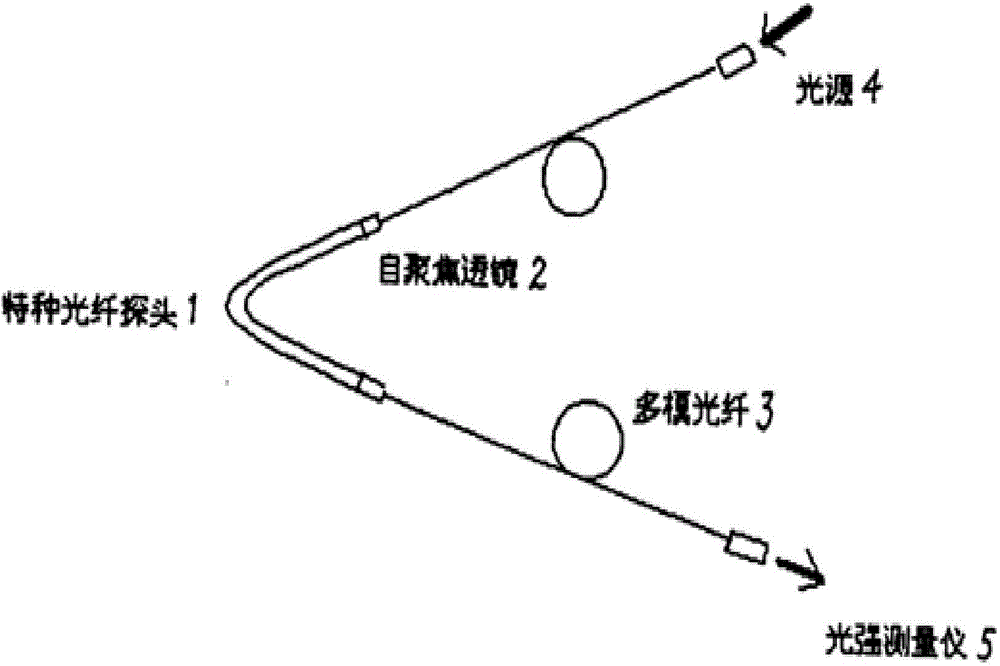
[0011] As shown in Figure 1, the optical fiber sensor designed by the present invention includes a V-shaped special optical fiber probe 1 and two multimode optical fibers 3 coupled with the self-focusing lens 2, and the V-shaped special optical fiber probe 1 adopts a Φ1.8mm , about 30mm long special optical fiber rod, two cross-sections are ground and polished and then bent into a V-shape under high temperature. The self-focusing lens 2 and the fiber probe 1 are bonded with optical resin to form a fiber sensor. The optical fiber probe 1 of the optical fiber sensor is directly placed in the transformer oil, and the two leading ends of the two multimode optical fibers 3 are respectively connected to the light source 4 and the light intensity measuring instrument 5 .

[0012] The above-mentioned optical fiber sensor is based on the following principle: the two leading ends of the multimode optical fiber 3 are respectively connected to the light source 4 and the light intensity me...


PUM


Abstract

The invention discloses an optical fiber sensor for measuring electrified capacity of transformer oil. The optical fiber sensor for measuring the electrified capacity of the transformer oil comprises a V-shaped special optical fiber probe and two multi-mode optical fibers coupled to a self-focusing lens. After two fracture surfaces of a special optical fiber rod are ground and polished, the special optical fiber rod is bent into the V-shaped special optical fiber probe; one ends of the two multi-mode optical fibers are respectively coupled to the self-focusing lens; the self-focusing lens is adhered to the optical fiber probe; the optical fiber probe of the optical fiber sensor is directly placed in the transformer oil; and two leading-out ends of the two multi-mode optical fibers are respectively connected with a light source and a light intensity measuring instrument. According to the characteristic that the light gathering capabilities of the optical fibers in media with different dielectric constants are different, change of the electrified capacity of the transformer oil can be monitored by monitoring the change conditions of transmittance of the optical fiber probe in the transformer oil. The optical fiber sensor is simple in structure and high in sensitivity and is convenient and practical.

Description

technical field [0001] The invention relates to an on-line monitoring technology for large-scale power transformers, in particular to an optical fiber sensor for measuring the electric quantity of transformer oil. Background technique [0002] Generally, large power transformers are almost all filled with transformer oil in order to improve their insulation and heat dissipation. However, since oil is a hydrocarbon, it will age under the influence of electricity, heat and the environment, thereby reducing its insulation performance. In addition, due to various reasons such as moisture in the oil, force displacement of components and coils, and scars on the outside of the winding wires, etc., a discharge phenomenon occurs inside the transformer. The initial discharge is small, but as time goes by, the discharge continues to increase. The charge diffuses around and dissolves in the transformer oil; on the other hand, in the high-power transformer, the oil is forced to flow, an...

Claims


Application Information

Patent Timeline
Patent Type & Authority Applications(China)
IPC IPC(8): G01R31/12G01J1/00
Inventor 鞠洪建
Owner DALIAN KANGSAIPU TECH DEV
Learn More