Supercharge Your Innovation With Domain-Expert AI Agents!

Control system model using retarder and exhaust brake for combined braking and building method of control system model

A technology of retarder braking and exhaust braking, which is applied in general control systems, control/regulation systems, instruments, etc., can solve the problems of low cost, increased development cycle, and high cost, so as to improve work efficiency and economic efficiency Benefits, the effect of shortening the cycle

Inactive Publication Date: 2015-05-20
SHAANXI FAST GEAR CO
View PDF5 Cites 14 Cited by
  • Summary
  • Abstract
  • Description
  • Claims
  • Application Information

AI Technical Summary

Problems solved by technology

[0003] The R&D and application of electronically controlled hydraulic retarders abroad have made considerable progress, such as: German CF, German Voith, Swedish Scania, General Motors' Allison series hydraulic retarders, etc. However, although the technology of foreign hydraulic retarders is mature, the cost is relatively high, so domestic main engine manufacturers have not been able to carry out large-scale matching. The development of domestic hydraulic retarders has been pioneered by Fast. The retarder technology continues to mature and the hydraulic retarder has been introduced to the market, which has been recognized by users, and the cost is much lower than that of foreign manufacturers.
[0004] At present, the electronic control systems of hydraulic retarders in China are all in the form of handwritten codes, but many parameters of the control system need repeated experiments to determine, which is relatively expensive for bench experiments and loading tests. Changes will not only increase the development cost, but also increase the development cycle

Method used


Image

  • Control system model using retarder and exhaust brake for combined braking and building method of control system model
  • Control system model using retarder and exhaust brake for combined braking and building method of control system model
  • Control system model using retarder and exhaust brake for combined braking and building method of control system model

Examples


Embodiment Construction

[0041] Below in conjunction with accompanying drawing, the present invention is described in further detail:

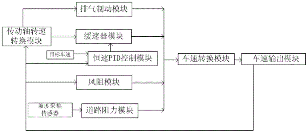
[0042] A method for establishing a control system model of retarder and exhaust brake combined braking, including:

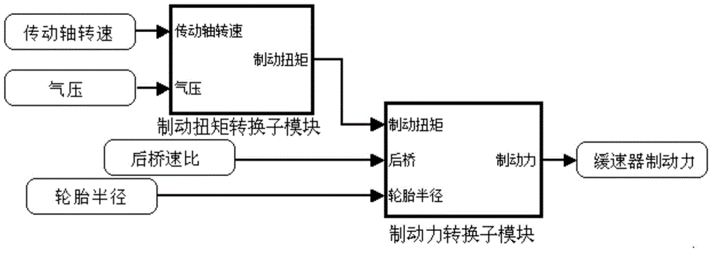
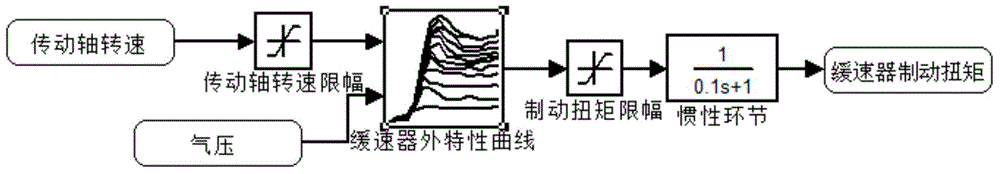
[0043] 1) Obtain the external characteristic curve of the retarder through repeated bench experiments, that is, the relationship between air pressure-transmission shaft speed-retarder braking torque;

[0044] 2) Accurate exhaust brake external characteristic curve is obtained through repeated drum rotation, that is, the relationship between engine speed and exhaust brake power;

[0045] 3) According to the tire radius, the speed ratio of the rear axle and the vehicle speed, the speed of the drive shaft is obtained. Based on the external characteristic curve of the retarder, the braking torque of the retarder is obtained according to the air pressure and the speed of the drive shaft. The method is based on the air pressure-drive shaft The speed-braking ...


PUM


Abstract

The invention discloses a control system model using a retarder and an exhaust brake for combined braking and a building method of the control system model. The method includes: acquiring the air pressure-transmission shaft rotation speed-retarder brake torque relation through repeated bench tests; acquiring the engine rotation speed-exhaust brake torque relation through repeated drum rotation; respectively acquiring retarder brake force, exhaust brake force, air resistance brake force and road resistance brake force through different modules; overlapping the brake force into total brake force, converting the brake force into acceleration, the acceleration is converted into speed, and a vehicle constant-speed downhill function and a vehicle brake function are achieved. The method has the advantages that MATLAB / SIMULINK is used as a tool to build a combined brake control system using the retarder including environmental resistance and the exhaust brake, and precise retarder and exhaust brake combined brake effects are achieved by fast changing control system model parameters.

Description

technical field [0001] The invention belongs to the technical field of vehicle braking, and in particular relates to a control system model of retarder and exhaust braking combined braking and a method for establishing the same. Background technique [0002] Heavy-duty vehicles under complex working conditions, such as: long downhill braking, frequent braking on flat roads, etc., the braking intensity of the driving main brake is greatly increased compared with general working conditions, such as: accelerated wear of the brakes, accelerated brake linings Recession, etc., reaching a certain degree of severity, can lead to failure of the main brake, resulting in traffic accidents. The hydraulic retarder can realize constant speed and graded braking functions, and can effectively reduce the pressure of the main brake. Compared with other auxiliary braking (engine braking, eddy current retarder), it has the advantages of large braking torque, stable braking, low noise, long lif...

Claims


Application Information

Patent Timeline
IPC IPC(8): G05B17/02
Inventor 张小明马东闯
Owner SHAANXI FAST GEAR CO
Features
  • R&D
  • Intellectual Property
  • Life Sciences
  • Materials
  • Tech Scout
  • Unparalleled Data Quality
  • Higher Quality Content
  • 60% Fewer Hallucinations
Learn More