DC bias oversampling digital-to-analog converter

A digital-to-analog converter, DC bias technology, applied in the direction of digital-to-analog converters, etc., can solve problems such as complex circuits

Inactive Publication Date: 2015-05-20
SUZHOU BATELAB MICROELECTRONICS
View PDF2 Cites 5 Cited by
  • Summary
  • Abstract
  • Description
  • Claims
  • Application Information

AI Technical Summary

Problems solved by technology

For this multi-bit implementation, the chopper 18 is not only real

Method used


Image

  • DC bias oversampling digital-to-analog converter
  • DC bias oversampling digital-to-analog converter
  • DC bias oversampling digital-to-analog converter

Examples


Embodiment Construction

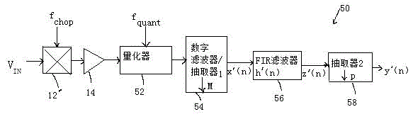
[0037] refer to image 3 , according to the principles of the present invention, the digital-to-analog converter 50 is an improved digital-to-analog converter, and the converter 50 includes an analog chopper 12, a buffer amplifier 14, a quantizer 52, a digital filter and a decimator 154, an FIR filter 56 and decimator 258 .

[0038] Analog chopper 12 chops the analog input signal with a square wave , the frequency of the square wave is , successively reversed polarity. The analog chopper 121 can be realized by any well-known analog chopper circuit. For example, if Figure 4 shown, if the input signal is a differential signal

[0039] Analog chopper 12 can be implemented with cross-coupled switches 24 , 25 , 26 and 27 . Switch 24 is controlled by the chopping signal Q, and is coupled to and between. Switch 25 is controlled by the chopping signal Q and is coupled to and and between. Switch 26 is controlled by a complementary chopping signal {draw a l...


PUM


Abstract

The invention discloses a DC bias oversampling digital-to-analog converter. A method and a device for an oversampling digital-to-analog converter with improved DC bias are provided. The DC bias oversampling digital-to-analog converter comprises a digital-to-analog converter; and the digital-to-analog converter comprises an oversampling quantizer, such as a single-bit or multi-bit Delta-Sigma regulator, a successive approximation quantizer, a dynamic quantizer, or a quantized or other proper oversampling quantized pipeline system device. Through limited components, a method for broadband attenuation for digital output of the digital-to-analog converter is provided.

Description

technical field [0001] The present invention relates to an oversampling analog-to-digital converter. More particularly, the present invention relates to methods and apparatus for improving the offset drift characteristics of DC current bias and oversampling analog-to-digital converters. Background technique [0002] Converting a continuous analog signal to a discrete digital representation requires anti-aliasing filtering, sampling and quantization. An antialiasing filter ensures that the analog input signal is band limited prior to sampling. at discrete time intervals , a sampler samples the filtered input signal, and Fs is the sampling frequency. The sampling frequency is at least twice the bandwidth of the filtered analog input signal. A quantizer converts samples into a set of discrete values. A traditional digital-to-analog converter performs sampling and quantization, while separate discrete components or integrated circuits perform anti-aliasing. [0003] In co...

Claims


Application Information

Patent Timeline
IPC IPC(8): H03M1/66
Inventor 不公告发明人
Owner SUZHOU BATELAB MICROELECTRONICS
Why Eureka
Try Eureka