Frequency mixer, frequency mixing method and optical receiver

A mixer and frequency mixing technology, applied in the field of communication, can solve the problems of complex AWG structure design, large number of arrayed waveguides, large size, etc., and achieve the effect of small transmission loss and coupling loss, small size, and cost saving of devices

Active Publication Date: 2015-05-20
HUAWEI TECH CO LTD
View PDF7 Cites 13 Cited by
  • Summary
  • Abstract
  • Description
  • Claims
  • Application Information

AI Technical Summary

Problems solved by technology

However, the design of the AWG structure in this scheme is relatively complicated, the number of arrayed waveguides is large, the size is large (generally in the order of millimeters), and the loss is also high. The insertion loss of a single device is greater than 5dB

Method used


Image

  • Frequency mixer, frequency mixing method and optical receiver
  • Frequency mixer, frequency mixing method and optical receiver
  • Frequency mixer, frequency mixing method and optical receiver

Examples


Embodiment Construction

[0037] The following will clearly and completely describe the technical solutions in the embodiments of the present invention with reference to the accompanying drawings in the embodiments of the present invention. Obviously, the described embodiments are only some, not all, embodiments of the present invention. Based on the embodiments of the present invention, all other embodiments obtained by persons of ordinary skill in the art without creative efforts fall within the protection scope of the present invention.

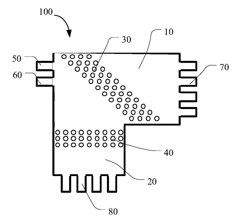
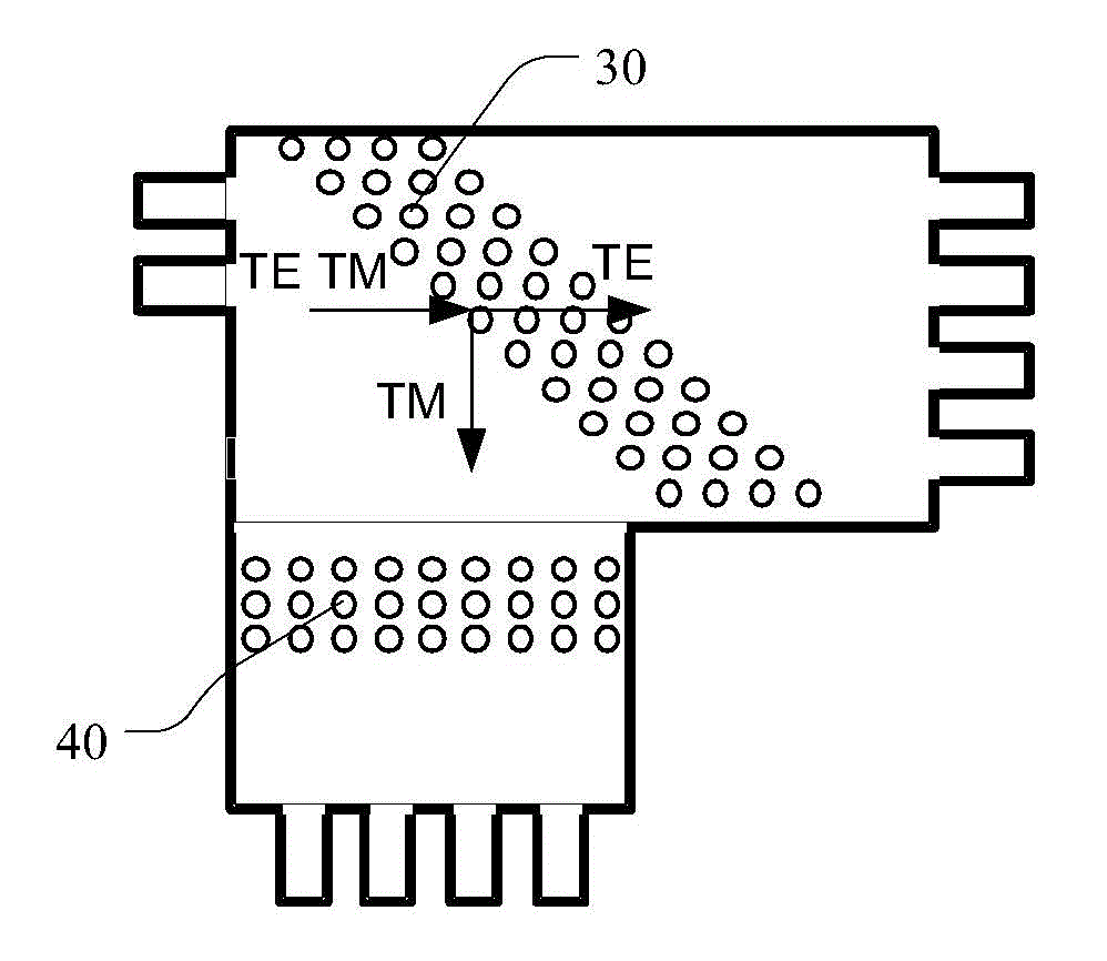
[0038] see figure 1 , is a schematic diagram of a mixer 100 provided by an embodiment of the present invention. The mixer 100 includes a first multimode interference region 10, a second multimode interference region 20, a first photonic crystal array 30, a polarized light input waveguide 50, a local oscillator light input waveguide 60, a first output waveguide array 70, Second output waveguide array 80 .

[0039] The polarized light input waveguide 50 is coupled ...


PUM


Abstract

An embodiment of the invention discloses a frequency mixer, which comprises a polarized light input waveguide, a local oscillator light input waveguide, a first output waveguide array, a second output waveguide array, a first multimode interference area, a second multimode interference area and a first photonic crystal array, wherein the polarized light input waveguide is coupled to the first multimode interference area, polarized light comprises first polarization state light and second polarization state light, which are orthogonal to each other; the local oscillator light input waveguide is coupled to the first multimode interference area, the first multimode interference area is coupled to the second multimode interference area, and the first multimode interference area and the second multimode interference area are used for carrying out frequency mixing on the polarized light and the local oscillator light; the first photonic crystal array is coupled in the first multimode interference area and is used for separating the polarized light to the first polarization state light and the second polarization state light. The frequency mixer has the advantages of smaller size and capabilities of reducing the complexity of the device, improving the integration level and saving the device cost. In addition, a frequency mixing method and an optical receiver are also disclosed.

Description

technical field [0001] The invention relates to the technical field of communication, in particular to a frequency mixer, a frequency mixing method and an optical receiver. Background technique [0002] With the rapid development of broadband services, core routers have introduced 100Gbps Ethernet interfaces, so backbone network equipment must support long-distance transmission of 100Gbps services. The Optical Internetworking Forum (OIF) standard organization prefers the optical modulation of Polarization multiplexed Quadrature Phase Shift keying (Polarization multiplexed Quadrature Phase Shift keying, PM-QPSK) for 100Gbps line-side transmission in the white paper of the transmission framework. The introduction of polarization multiplexing technology can double the capacity of transmitted optical signals. The rise of this technology means that the receiver needs to introduce a coherent detection method. [0003] In the existing coherent receiving system, the modulated optic...

Claims


Application Information

Patent Timeline
Patent Type & Authority Applications(China)
IPC IPC(8): H04B10/67
Inventor 周治平洪婷婷宋小鹿李艳萍易华祥王兴军
Owner HUAWEI TECH CO LTD
Why Eureka
Try Eureka