Light source device

A light source device and reference voltage technology, which is applied in the direction of light source, electric light source, lighting device, etc., can solve the problems of feedback resistor burning, feedback resistor power consumption increase, power waste, etc., and achieve the effect of reducing cross-voltage

Inactive Publication Date: 2015-05-20
CORETRONIC (SUZHOU) CO LTD
View PDF5 Cites 4 Cited by
  • Summary
  • Abstract
  • Description
  • Claims
  • Application Information

AI Technical Summary

Problems solved by technology

However, if the light-emitting element is connected in series with the feedback resistor, if the driving voltage received by the light-emitting element is a high voltage (for example, 200 volts), the current flowing through the light-emitting element will become high, and the voltage across the feedback resistor will change. high
At this time, the power consumption of the feedback resistor will increase, resulting in waste of power, and excessive cross-voltage may cause the feedback resistor to burn out

Method used


Image

  • Light source device
  • Light source device
  • Light source device

Examples


Embodiment Construction

[0018] The foregoing and other technical content, features, and effects of the present invention will be clearly presented in the detailed description of multiple embodiments below with reference to the drawings. The directional terms mentioned in the following embodiments, such as "upper", "lower", "front", "rear", "left", "right", etc., only refer to the directions of the attached drawings. Therefore, the directional terms used are used to illustrate rather than to limit the present invention.

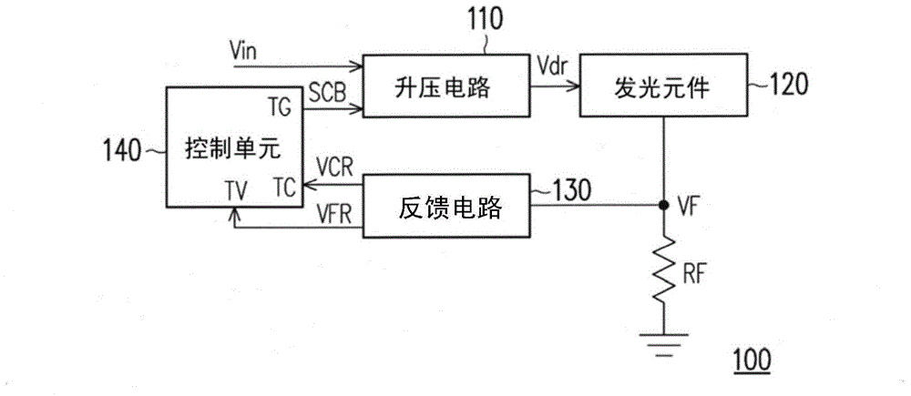
[0019] figure 1 It is a system schematic diagram of a light source device according to an embodiment of the invention. Please refer to figure 1 In this embodiment, the light source device 100 includes a booster circuit 110, a light emitting element 120, a feedback circuit 130, a control unit 140, and a feedback resistor RF. The boost circuit 110 receives the input voltage Vin and the boost control signal SCB, and is used to determine the boost multiple (ie, the magnification) of the in...


PUM


Abstract

A light source device comprises a boosting circuit, a light emitting component, a feedback resistor, a feedback circuit and a control unit. The boosting circuit decides boosting times of input voltage according to boosting controls signals of the control unit and provides driving voltage to the light emitting component. The feedback resistor is serially connected with the light emitting component. The feedback circuit receives feedback voltage provided by the feedback resistor and provides feedback reference voltage and control reference voltage to the control unit, and the feedback reference voltage is higher than the feedback voltage. The control unit adjusts duty cycle of the boosting control signals according to the received control reference voltage.

Description

Technical field [0001] The present invention relates to a light source device, in particular to a light source device with light emitting diodes. Background technique [0002] With the evolution of lighting technology, light sources used in lamps have evolved from incandescent bulbs and fluorescent tubes to the rapidly developing light emitting diodes (LEDs) in recent years. Light-emitting diodes have many advantages such as power saving, long service life, environmental protection, fast start-up, small size, etc., and the power that light-emitting diodes can reach gradually increases with the maturity of technology, so light-emitting diodes have gradually been used in general The trend of lighting to replace fluorescent tubes. [0003] In the light source device, the light-emitting element is connected in series with at least one feedback resistor to determine the current flowing through the light-emitting element through the feedback voltage provided by the feedback resistor. I...

Claims


Application Information

Patent Timeline
Patent Type & Authority Applications(China)
IPC IPC(8): H05B37/02
Inventor 邓天宇
Owner CORETRONIC (SUZHOU) CO LTD
Why Eureka
Try Eureka