Ultrasonic apparatus and vibration device applied to ultrasonic apparatus

A technology of vibrating device and ultrasonic instrument, which is applied in the field of ultrasonic instrument, can solve the problems of resource waste, cost increase, ultrasonic probe size increase, etc., and achieve the effect of convenient use and cost reduction

Active Publication Date: 2015-05-27
GENERAL ELECTRIC CO
View PDF9 Cites 19 Cited by
  • Summary
  • Abstract
  • Description
  • Claims
  • Application Information

AI Technical Summary

Problems solved by technology

However, since the vibrator is embedded in the ultrasonic probe, the size of the ultrasonic probe will increase accordingly, and the cost will also increase
In addition, the function of applying the vibrator to the ultrasonic instrument is only a small function, and it is not necessary to use this function in many cases, or it is not needed at all in some applications, thus causing a waste of resources virtually.

Method used


Image

  • Ultrasonic apparatus and vibration device applied to ultrasonic apparatus
  • Ultrasonic apparatus and vibration device applied to ultrasonic apparatus
  • Ultrasonic apparatus and vibration device applied to ultrasonic apparatus

Examples


Embodiment Construction

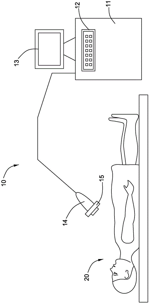
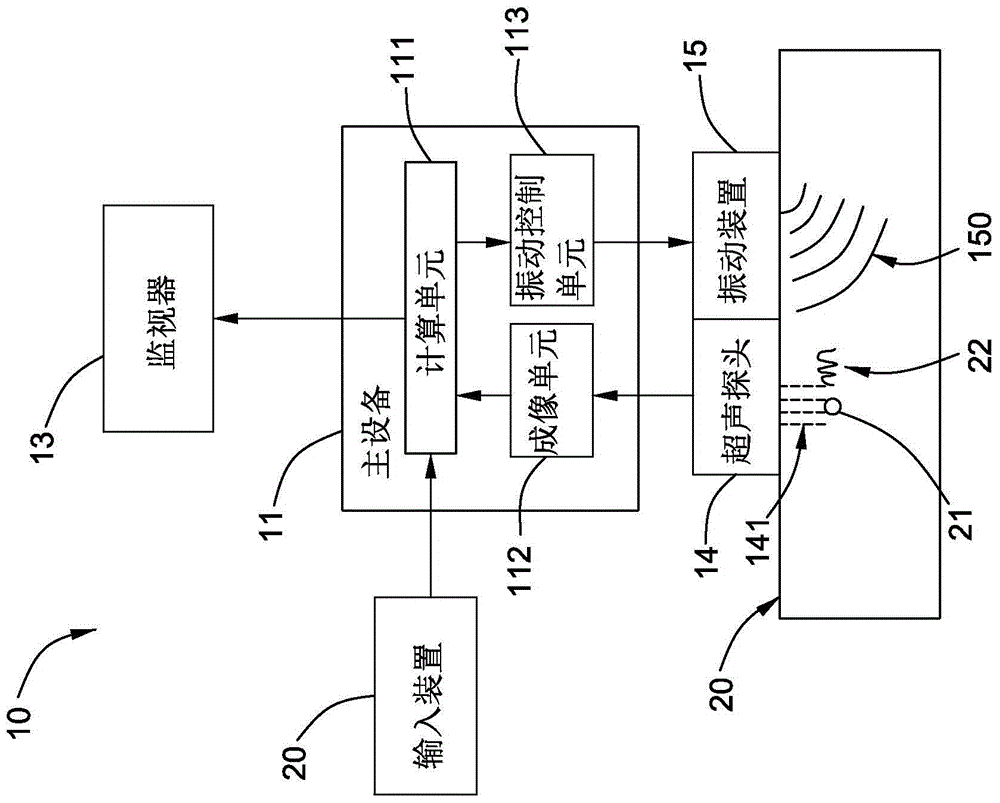
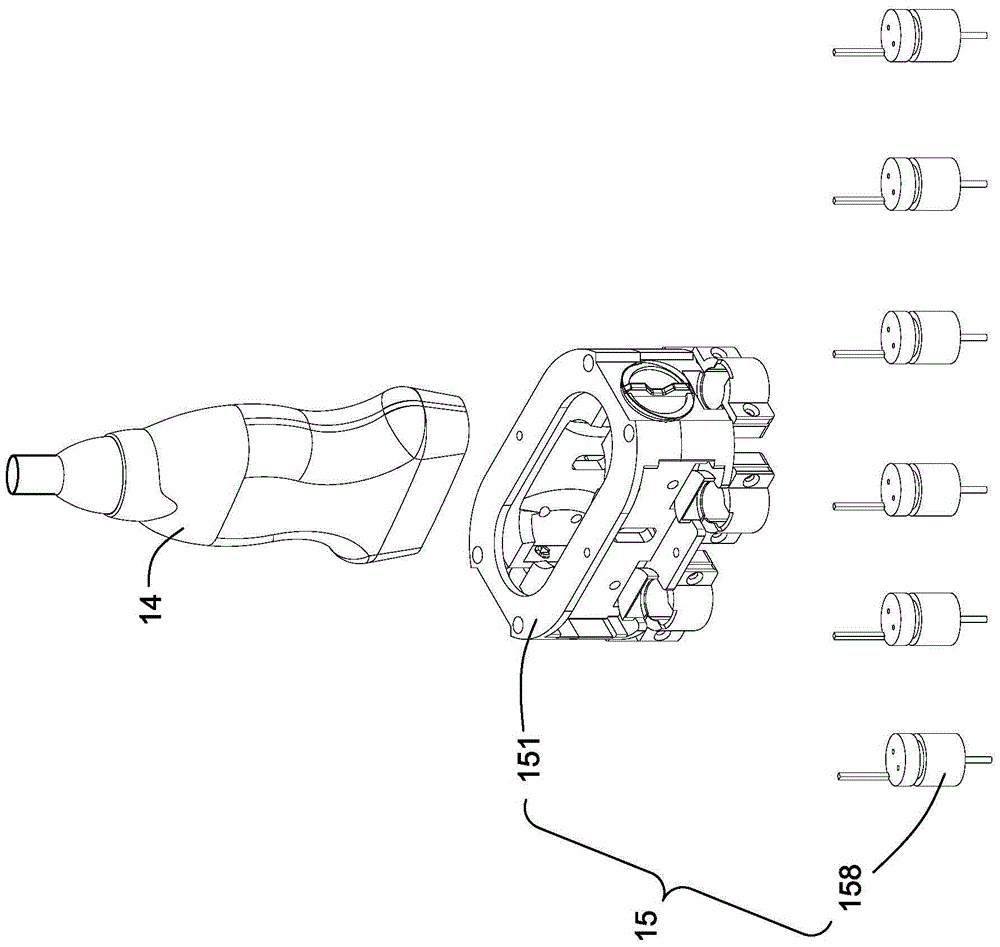
[0027] Specific implementations of the present invention will be described below. It should be noted that in the process of specific descriptions of these implementations, for the sake of concise description, it is impossible for this specification to describe all the features of the actual implementations in detail. It should be understood that, in the actual implementation process of any embodiment, just like in the process of any engineering project or design project, in order to achieve the developer's specific goals and to meet system-related or business-related constraints, Often a variety of specific decisions are made, and this can vary from one implementation to another. In addition, it will be appreciated that while such development efforts may be complex and lengthy, the technology disclosed in this disclosure will be Some design, manufacturing or production changes based on the content are just conventional technical means, and should not be interpreted as insuffic...


PUM


Abstract

The invention relates to an ultrasonic apparatus and a vibration device applied to the ultrasonic apparatus. The ultrasonic apparatus comprises an ultrasonic probe and the vibration device. The vibration device comprises a receiving frame, a mounting rack, a clamping device, and at least one mechanical vibrator mounted on the mounting rack, wherein a first receiving opening for receiving the ultrasonic probe is formed in the receiving frame, and the dimension of the first receiving opening is greater than the outer diameter dimension of the ultrasonic probe; a second receiving opening corresponding to the first receiving opening is formed in the mounting rack; the mounting rack is connected with the receiving frame, and after connection, the first receiving opening corresponds to the second receiving opening. The clamping device is arranged between the receiving frame and the mounting rack and is capable of selectively clamping the ultrasonic probes different in outer diameter dimension.

Description

technical field [0001] The invention relates to an ultrasonic instrument, in particular to a vibrating device that can be flexibly applied to an ultrasonic instrument. Background technique [0002] As an emerging tissue imaging technique, shear wave-based elasticity imaging or elastography has made great progress in recent years. Generally speaking, some mechanical properties of tissues, such as viscoelasticity, can be determined by performing shear wave elastography, and then the obtained viscoelastic information can assist in determining whether the specific tissue is associated with certain pathological symptoms. Generally speaking, several operational steps are involved in the actual shear wave elastography, one of which is to apply acoustic radiation driving force to the region of interest of the target tissue through an ultrasound probe or an external device such as an external vibrator Or a mechanical wave impetus under which shear waves are generated in the region o...

Claims


Application Information

Patent Timeline
Patent Type & Authority Applications(China)
IPC IPC(8): A61B8/00
CPCA61B8/44
Inventor 程刚C·R·哈扎德韩晓东刘震宇
Owner GENERAL ELECTRIC CO
Why Eureka
Try Eureka