Hydraulic-driven multi-joint industrial robot

An industrial robot and multi-joint technology, applied in manipulators, manufacturing tools, program-controlled manipulators, etc., can solve problems such as small load/weight ratio, complex topology, and flexible workspace to be improved, and achieve the effect of large self-weight ratio

Active Publication Date: 2015-05-27
SHANDONG UNIV
View PDF11 Cites 18 Cited by
  • Summary
  • Abstract
  • Description
  • Claims
  • Application Information

AI Technical Summary

Problems solved by technology

[0004] Although the mechanical arm disclosed in the above literature has a certain number of degrees of freedom, its topology is complex, its load / weight ratio is small, and its flexible working space still needs to be improved.

Method used


Image

  • Hydraulic-driven multi-joint industrial robot
  • Hydraulic-driven multi-joint industrial robot
  • Hydraulic-driven multi-joint industrial robot

Examples


Embodiment Construction

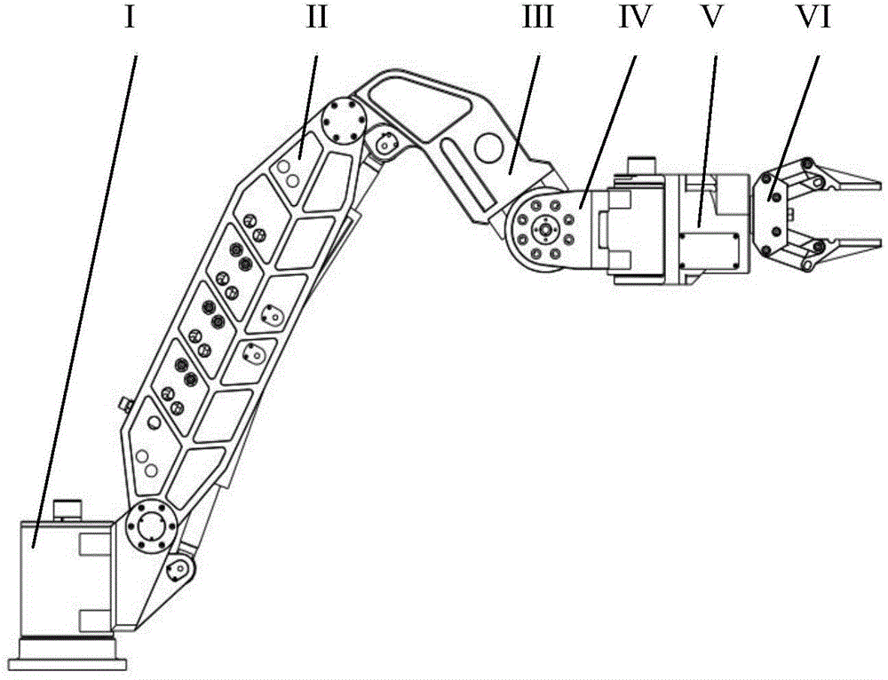
[0034] Hydraulic drive multi-joint industrial robot of the present invention, as figure 1 As shown, it includes six connecting rod components connected in sequence and a hydraulic control component VII. The six link parts are link part I, link part II, link part III, link part IV, link part V and link part VI.

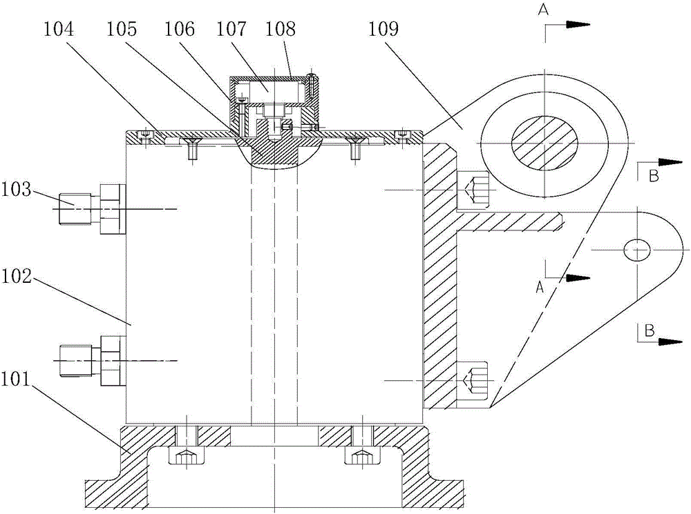
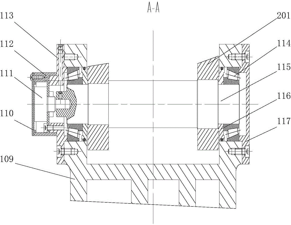
[0035] The structure of connecting rod part I is as figure 2 , image 3 and Figure 4 As shown, it includes a base 101 , a swing cylinder 102 , an encoder 107 , a connecting rod 109 , an encoder 111 , a shaft 115 and a shaft 118 . The base 101 is used to fix the robot on the ground or other mobile carriers. The lower end of the inner shaft of the swing oil cylinder 102 is fixed on the base 101 with screws, and the upper end of the outer ring of the swing oil cylinder 102 is fixed with an oil cylinder end cover 104 with screws. The encoder 107 is fixed in the encoder housing 106, and the encoder housing 106 is fixed on the cylinder end cover 104 with screws, and t...


PUM


Abstract

The invention discloses a hydraulic-driven multi-joint industrial robot. The hydraulic-driven multi-joint industrial robot comprises a connecting rod part I, a connecting rod part II, a connecting rod part III, a connecting rod part IV, a connecting rod part V and a connecting rod part IV as well as a hydraulic control part VII which are connected in sequence, wherein joints of the connecting rod parts are connected through rotary joints; each rotary joint is connected with a hydraulic oil cylinder, and a coder is mounted on each rotary joint; a double-finger grip is arranged on the connecting rod part VI, the fingers of the grip are connected with a linear hydraulic oil cylinder; an oil path of each hydraulic oil cylinder is communicated with the hydraulic control part VII, and an electro-hydraulic servo valve is arranged in the hydraulic control part. The robot adopts a fully serial structure form and has six rotary joints, the coder is mounted on each rotary joint, and the grip is mounted on the tail end, so that a load/dead load ratio is large. The hydraulic-driven multi-joint industrial robot is especially suitable for transporting, stacking or other large-load working stations or being mounted on a mobile carrier as a mobile operation mechanical arm.

Description

technical field [0001] The invention relates to a hydraulic servo-driven multi-joint robot, which belongs to the technical field of industrial robots. Background technique [0002] With the rapid development of industrial technology, industrial robots are widely used in assembly, welding, handling and other industries, which greatly improves the automation level of industrial production and liberates humans from repetitive labor or extremely harsh working environments. Almost all existing industrial robots are driven by servo motors and RV or harmonic reducers, which have high position accuracy and mature technology, but their load / weight ratio is small, and they are not suitable for underwater or working environments with strong electromagnetic interference . At present, there are hydraulic servo-driven multi-joint robots abroad, but there are no mature products in China. [0003] Chinese patent document CN1035380701A discloses a 5-DOF hydraulic servo manipulator, which u...

Claims


Application Information

Patent Timeline
Patent Type & Authority Applications(China)
IPC IPC(8): B25J9/06B25J9/14
Inventor 荣学文宋锐李贻斌柴汇初国庆唐兴鹏
Owner SHANDONG UNIV
Why Eureka
Try Eureka