Tidying tool of injection molding parts

A technology for injection molding parts and tools, applied in the field of injection molding parts finishing tools, can solve the problems of rising production costs, complicated equipment, and laboriousness.

Inactive Publication Date: 2015-05-27
常州大恒塑料制品有限公司
View PDF0 Cites 0 Cited by
  • Summary
  • Abstract
  • Description
  • Claims
  • Application Information

AI Technical Summary

Problems solved by technology

Arranging these injection molded parts by hand, due to the large quantity, is a constant repetitive work, which is usually laborious and the work efficiency is not high
[0003] At present, there are also some intelligent packing machines and sort

Method used


Image

  • Tidying tool of injection molding parts

Examples


Embodiment Construction

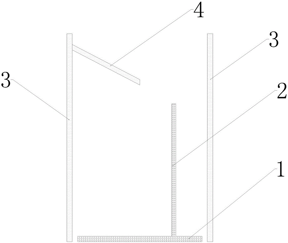
[0012] according to figure 1 The shown finishing tool for injection molded parts has a base 1, a needle 2, a bracket 3, and a slide 4. The base 1 is placed horizontally at the exit of the injection molding machine, and the needle 2 is vertically fixed on the base 1. The described The bracket 3 is separated from the base 1 and is placed around the base 1 . The upper wall of the bracket 3 has a slide 4 .

[0013] Here if the injection molded part is a disc with a hole shape, then the support can be set to a cylindrical barrel shape.

[0014] When in use, the injection molded part slips from the exit of the injection molding machine, first falls on the landslide 4, slides down along the slope of the landslide 4, and then the injection molded part falls on the threading needle 2, and then falls to the base along the threading needle 2 1 above.

[0015] In such a cyclical operation, the injection molded parts will pass through the threading needle 2 one by one and neatly stacked ...


PUM


Abstract

The invention discloses a tidying tool of injection molding parts. The tidying tool can quickly and conveniently tidy up injection molding parts produced through an injection molding machine, especially hole-shaped and frame-shaped injection molding parts so as to facilitate subsequent processing, packaging or transit shipment. The tidying tool is placed in an outlet of the injection molding machine, after the injection molding parts are produced, the injection molding parts can slip into the tidying tool and be arrayed tidily, so manual tidying time is saved and work efficiency is improved. The tidying tool is simple in structure and low in cost, and can be widely popularized and utilized.

Description

technical field [0001] The invention relates to a sorting tool for injection molded parts, in particular to a sorting tool for sorting hole-shaped and frame-shaped injection molded parts. Background technique [0002] Injection molded parts are produced by injection molding machines. Generally speaking, injection molded parts slide out from the exit of the injection molding machine and directly enter the collection box. They are scattered in the box in a disorderly manner. Workers need to manually organize these injection molded parts for subsequent use. Processing, packaging or transit handling. Arranging these injection molded parts by hand is a constant repetitive work due to the large quantity, which is usually laborious and the work efficiency is not high. [0003] At present, there are also some intelligent packing machines and sorting machines on the market. Although they have high work efficiency, these devices are relatively complicated and expensive. The cost wil...

Claims


Application Information

Patent Timeline
IPC IPC(8): B65G57/03B29C45/17
CPCB65G57/03B29C45/17
Inventor 吴旭日
Owner 常州大恒塑料制品有限公司
Why Eureka
Try Eureka