
Eureka
For R&D, Eureka makes reading and utilizing patents & technical documents easy.
Eureka AIR
Designed for self-driven R&D workflows. Generate viable solutions, solve complex R&D challenges, empower your innovation with AI.

Eureka Materials
Designed for material experts only. Revolutionize your material R&D, from search, analyze, to developing new materials.

TechResearch
Generate reliable direction feasibility study reports for your R&D in just a few steps.

TechSeek
Discover and master advanced knowledge NOW. Basics, ideas, possibilities, all at once.

TechMind
As an expert in R&D Theories, TechMind can generates customized viable solutions instantly.

TechRisk
Analyze your overall solution with one click, know your potential R&D risks in advance.

TechMonitor
Get weekly tech updates, stay abreast of the latest tech innovations and key insights.
System and method for treating exhaust gas
A technology for exhaust pipes and catalytic converters, which is applied in exhaust gas treatment, diagnostic devices for exhaust gas treatment devices, exhaust devices, etc., and can solve large spaces, HC and CO emission faults, and inability to mix urea with exhaust gas, etc. question
- Summary
- Abstract
- Description
- Claims
- Application Information
AI Technical Summary
Problems solved by technology
Method used
Image

Examples
Embodiment Construction
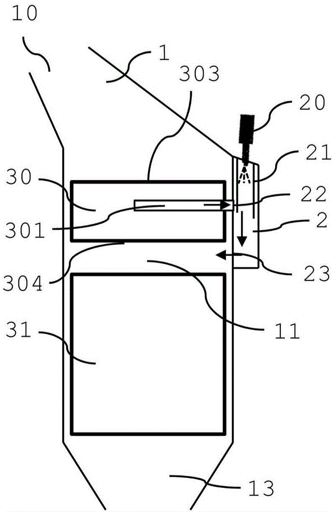
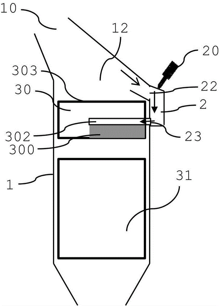
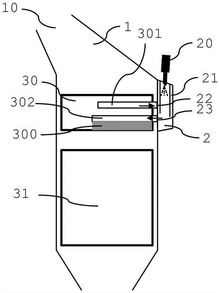
[0047] exist figure 1 Among them, the exhaust pipe inlet 10 is arranged at the upstream end of the exhaust pipe 1 . At the upstream end, the exhaust duct can be connected to the engine outlet. In the exhaust pipe 1 , an oxidation catalyst 30 such as a diesel oxidation catalyst (DOC) is arranged such that further downstream is a selective catalytic reactor (SCR) 31 . The SCR can, for example, also be combined with a diesel particulate filter (DPF) or be provided with a particulate filter function (SCRF). A bypass duct 2 with a bypass inlet 22 and a bypass outlet 23 is arranged adjacent to and substantially parallel to the exhaust duct 1 . The bypass pipe 2 bypasses a part of the exhaust pipe 1 and bypasses a part of the DOC 30, but not the entire DOC. The bypass pipe 2 is arranged on one side of the exhaust pipe 1 . However, the bypass duct can also be arranged to extend at least partially or completely around the circumference of the exhaust duct 1 . The bypass duct can bas...
PUM
 Abstract
Description
Claims
Application Information
 - R&D Engineer
- R&D Manager
- IP Professional
- Industry Leading Data Capabilities
- Powerful AI technology
- Patent DNA Extraction
Browse by: Latest US Patents, China's latest patents, Technical Efficacy Thesaurus, Application Domain, Technology Topic, Popular Technical Reports.
© 2024 PatSnap. All rights reserved.Legal|Privacy policy|Modern Slavery Act Transparency Statement|Sitemap|About US| Contact US: help@patsnap.com