gas turbine combustor

A technology for gas turbines and combustion chambers, which is applied in the direction of combustion chambers, continuous combustion chambers, combustion methods, etc., and can solve the problems of shortened life of sealing structures, impact of post-installation edge seal cooling, adverse effects of post-installation edge seals, etc.

Active Publication Date: 2020-01-03
CHINA UNITED GAS TURBINE TECH CO LTD
View PDF5 Cites 0 Cited by
  • Summary
  • Abstract
  • Description
  • Claims
  • Application Information

AI Technical Summary

Problems solved by technology

However, the distance between the installation edge after the transition section and the leading edge end wall of the first stage turbine vane is relatively large, and the cooling effect is limited. In order to achieve the required cooling effect, it is necessary to allocate more to the installation edge after the transition section than for the cooling itself required by the installation edge after the transition section Air, this part of the air cannot participate in combustion, which reduces the overall efficiency of the gas turbine
Another measure is to shorten the distance between the rear mounting edge of the transition section and the leading edge end wall of the turbine's first-stage vane, but this will have an adverse effect on the sealing of the rear installation edge of the transition section, and the damage caused by the turbine's first-stage vane The bow wave will have a great impact on the cooling of the rear mounting edge seal, resulting in shortened life of the seal structure or failure

Method used


Image

  • gas turbine combustor
  • gas turbine combustor
  • gas turbine combustor

Examples


Embodiment 1

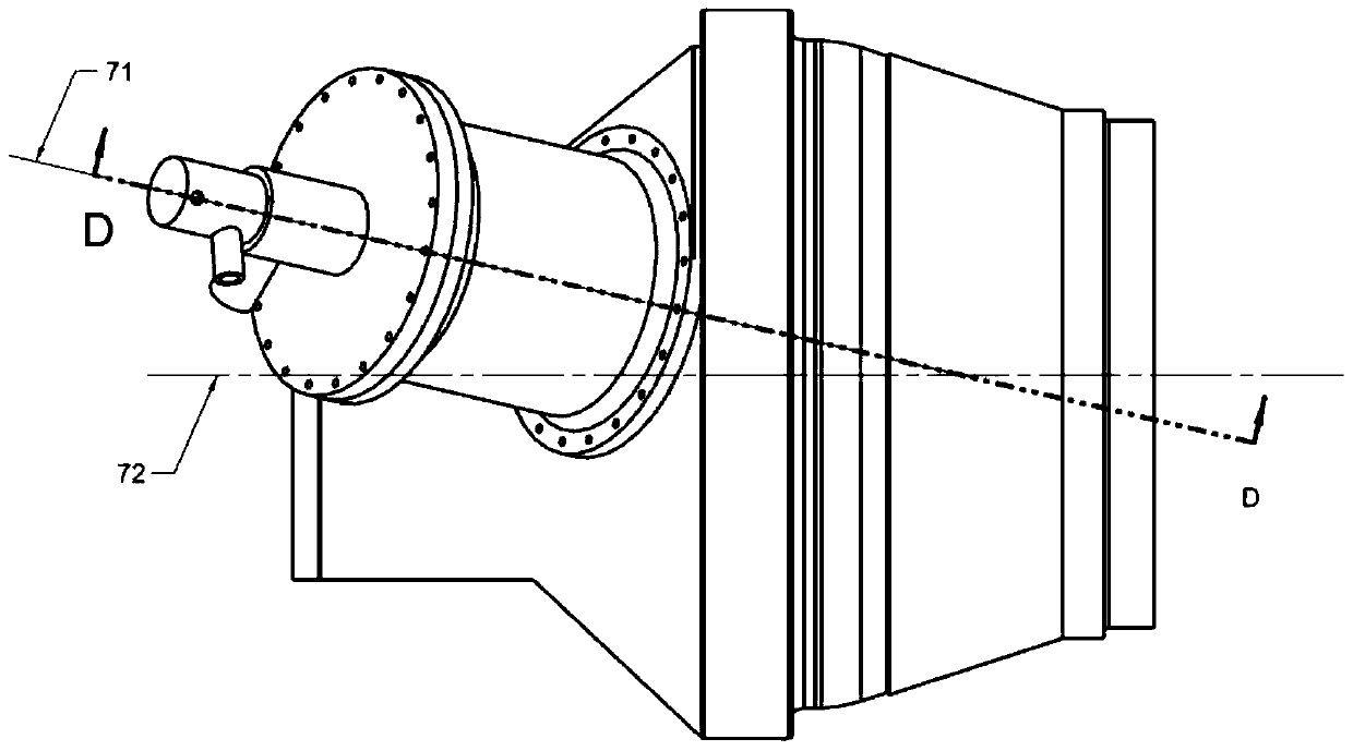
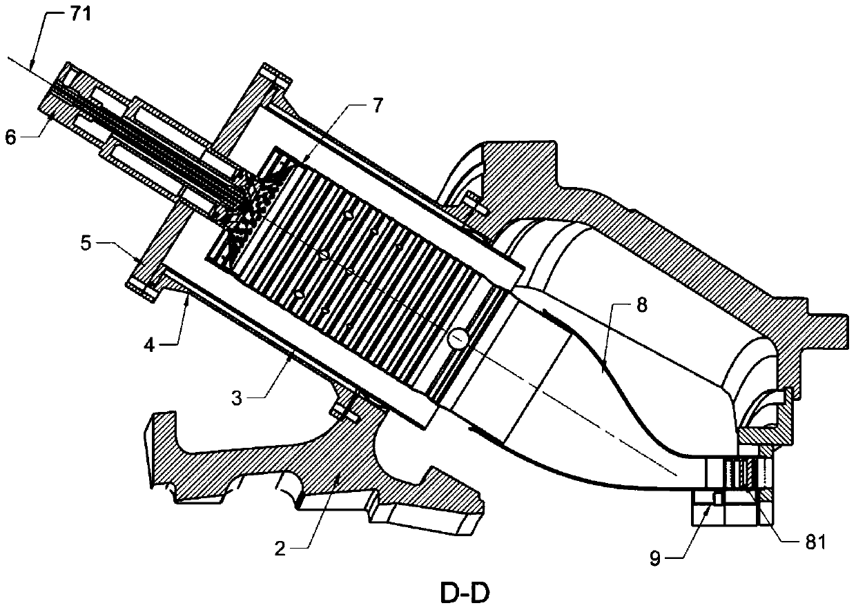
[0029] like Figure 1-4 As shown, the combustion chamber of the gas turbine in this embodiment includes: a fuel pressure cylinder 2, a casing 4 connected to the fuel pressure cylinder 2 at the rear end, an end cover 5 connected to the front end of the casing 4, and a nozzle 6 connected to the end cover 5 , the guide bush 3 connected to the inner side of the casing 4, the flame tube 7 located inside the guide bush 3 and the front end connected to the nozzle 6, and the transition section 8 whose inlet is connected to the rear end of the flame tube 7 .

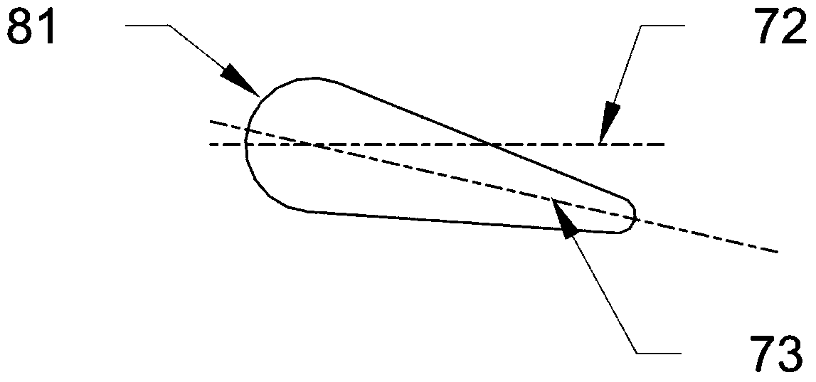
[0030] The outlet of the transition section 8 is provided with an outlet guide vane 81, the transition section 8 and the outlet guide vane 81 are an integrated structure, and the transition section 8 is provided with an air distribution chamber 9 at the outlet guide vane 81 and the front edge end wall 82 of the outlet guide vane . According to the different positions of the air distribution cavity 9, the cooling air flow control...

Embodiment 2

[0036] like Figure 5 As shown, the gas turbine combustor of this embodiment is different from that of Embodiment 1 in that the lower edge of the leading edge end wall 82 of the outlet guide vane is not provided with divergent cooling holes 93, but the air distribution chamber passage 94 and the outlet The internal cooling means of the vane 81 communicates.

[0037] Part of the cooling air that cools the leading end wall 82 of the outlet guide vane through the impact cooling hole 91 of the air distribution chamber 9 flows downstream into the internal cooling device of the outlet guide vane 81 , and the other part enters the outlet guide vane through the air distribution chamber 9 81 The cooling air from the internal cooling device is mixed, and finally enters the hot aisle 62 through the air film hole 61 on the surface of the outlet guide vane 81 .

[0038] The combustor of the gas turbine of the present invention is provided with a cooling structure at the integrated connect...


PUM


Abstract

The invention relates to the technical field of a gas turbine, and particularly discloses a combustion chamber of the gas turbine. The combustion chamber comprises a combustion pressure cylinder, a turbine box, an end cover, a spray nozzle, a flow guiding bush, a flame tube and a transition section, wherein the rear end of the turbine box is connected with the combustion pressure cylinder, the end cover is connected to the front end of the turbine box, the spray nozzle is connected to the end cover, the flow guiding bush is connected to the inner side of the turbine box, the flame tube is positioned in the flow guiding bush, the front end of the flame tube is connected with the spray nozzle, and an inlet of the transition section is connected with the rear end of the flame tube; an output guide vane is arranged in an output of the transition section, the transition section and the output guide vane are of an integrated structure, and air distribution cavities are formed in the output guide vane and the end wall of the front edge of the output guide vane of the transition section. According to the combustion chamber of the gas turbine, disclosed by the invention, the cooling flow of the end wall of the front edge of a primary stationary blade is saved, and the overall efficiency is increased.

Description

technical field [0001] The invention relates to the technical field of gas turbines, in particular to a combustion chamber of a gas turbine with a cooling structure at the integrated connection between a transition section and a turbine. Background technique [0002] The basic working process of a gas turbine is: the air entering the gas turbine is compressed by the compressor; it is mixed with fuel in the combustion chamber for combustion; the high-temperature and high-pressure gas at the outlet of the combustion chamber enters the turbine to drive the turbine to do work, and the temperature and pressure of the gas are in the turbine. Each stage of the stationary blade and moving blade is lowered step by step to convert part of the heat energy of the gas into mechanical energy, which drives the compressor to rotate, and the other part of the heat energy is converted into mechanical energy for power or power generation. [0003] Generally speaking, the middle and rear sectio...

Claims


Application Information

Patent Timeline
Patent Type & Authority Patents(China)
IPC IPC(8): F23R3/00
Inventor 方子文吕煊李珊珊杨旭
Owner CHINA UNITED GAS TURBINE TECH CO LTD
Why Eureka
Try Eureka