An internal circulation reactor

An internal circulation, reaction furnace technology, applied in furnaces, fluidized bed furnaces, furnace types, etc., can solve the problems of limited residence time, short residence reaction time, excessive heat loss and thermal expansion, and achieve controllable degree of reaction. Short residence time and wide controllable effect

Active Publication Date: 2016-07-13
CHANGSHA RES INST OF MINING & METALLURGY
View PDF9 Cites 0 Cited by
  • Summary
  • Abstract
  • Description
  • Claims
  • Application Information

AI Technical Summary

Problems solved by technology

Gao Zebin and Li Yongheng integrated fuel combustion, return air and reducing gas mixing, and magnetization roasting, and proposed a combustion, mixing and roasting integrated furnace (patent application number: 201320236723.2). The movement in the reactor can be approximated as a plug flow of gas-solid flow. The residence time of the material in the reactor is limited, usually from a few seconds to 1 minute. In order to make the material react completely, the temperature of the reactor needs to be increased, so that The cost of magnetization roasting is too high
[0004] Therefore, the external circulation fluidized roaster cannot meet the requirements of rapid separation reaction, the circulation equipment is huge, the heat loss and thermal expansion are too large, the roasting temperature of the ordinary fluidized roaster is too high, and the residence reaction time of the material in the roaster is short, etc. Defects, the development of an internal circulation fluidized reactor has important practical significance for the progress of fluidized roasting technology

Method used


Image

  • An internal circulation reactor
  • An internal circulation reactor
  • An internal circulation reactor

Examples


Embodiment Construction

[0025] The present invention will be described in further detail below in conjunction with the accompanying drawings and specific embodiments.

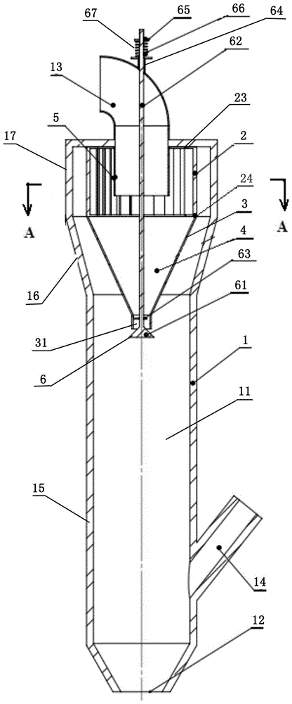
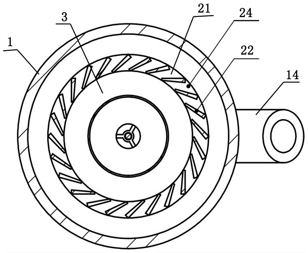
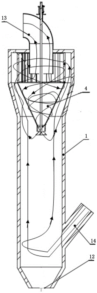
[0026] like figure 1 and figure 2 As shown, the internal circulation reaction furnace of the present invention comprises a furnace body 1 with a furnace chamber 11, the bottom of the furnace body 1 is provided with an air inlet 12, and the top of the furnace body 1 is provided with a reaction furnace outlet pipe 13, and the furnace body 1 A feed pipe 14 is provided on the side wall near the bottom, wherein the outlet pipe 13 of the reaction furnace is used to be connected with the gas-solid separation device, and the reaction product is obtained after separation; the feed pipe 14 is used to be connected with the feeding device , The material is fed into the furnace cavity 11 through the feed pipe 14; The upper part in the furnace cavity 11 is provided with an internal circulation part, and the internal circulation part includes an ...


PUM

PropertyMeasurementUnit
angleaaaaaaaaaa

Abstract

The invention discloses an internal circulation type reacting furnace. The internal circulation type reacting furnace comprises a furnace body with a furnace chamber, wherein a reacting furnace outlet pipe is arranged at the top of the furnace body; an internal circulation component is arranged on the upper part in the furnace chamber and comprises a guide inner cylinder, an air guide cylinder, an inverted conical cylinder connected to the bottom of the air guide cylinder, and a valve component; an internal circulation chamber is formed between the air guide cylinder and the inverted conical cylinder; a plurality of air guide passages used for guiding materials in the furnace chamber into the internal circulation chamber are arranged on the side wall of the air guide cylinder; the plurality of air guide passages are uniformly arranged around the axial line of the air guide cylinder at intervals; the included angle between the direction in which each air guide passage guides materials into the internal circulation chamber and the tangential line, at the corresponding air guide passage, of the air guide cylinder is an acute angle; a communicating opening communicating the furnace chamber to the internal circulation chamber is formed in the bottom of the inverted conical cylinder; the valve component is used for controlling the size of the communicating opening. The internal circulation type reacting furnace has the advantages that reaction temperature can be reduced, the energy-saving effect is better, the time required by complete reaction of materials with different granularity can be satisfied, the reaction degree is relatively controllable, and the like.

Description

technical field [0001] The invention relates to the technical field of ore dressing and metallurgy, in particular to an internal circulation type fluidized magnetization roasting reaction furnace. Background technique [0002] According to the relative movement of the material and the furnace wall in the reaction furnace, the gas-solid reaction state can be divided into two reaction forms: accumulation reaction and fluidization reaction. Compared with the accumulation state reaction form, the fluidization reaction process has the following characteristics: 1. The gas-solid heat and mass transfer speed is fast, and the heat transfer and mass transfer coefficients of fine-grained materials in the suspension state are higher than those in the accumulation state. 3,000 to 4,000 times the mass coefficient; 2. The reaction time is short, and the time required for the reaction in the fluidized state is greatly shortened compared with that in the stacked state; 3. The quality of the...

Claims


Application Information

Patent Timeline
Patent Type & Authority Patents(China)
IPC IPC(8): F27B15/00F27B15/02F27B15/18C22B1/10
Inventor 李家林陈雯张立刚刘小银严小虎陆晓苏彭泽友廖振鸿
Owner CHANGSHA RES INST OF MINING & METALLURGY
Why Eureka
Try Eureka