Three-dimensional gradient boundary transition device applied to wind field characteristic wind tunnel experiments of terrain model

A terrain model, wind tunnel test technology, applied in the direction of measurement device, aerodynamic test, machine/structural component test, etc., can solve the problem of high wind tunnel space requirements, difficult to apply wind tunnel test needs, separation and other problems

Active Publication Date: 2015-05-27
SOUTHWEST JIAOTONG UNIV +1
View PDF4 Cites 10 Cited by
  • Summary
  • Abstract
  • Description
  • Claims
  • Application Information

AI Technical Summary

Problems solved by technology

[0003] The existing transition device is mainly composed of multiple straight 30o slope plates spliced ​​at the boundary of the terrain model. When the incoming flow flows to the slope plate, the air velocity will increase along the slope and the pressure will increase due to the pressure of the slope. As it decreases, a forward pressure gradient will be generated. When the airflow reaches the intersection of the slope and the boundary of the terrain model, the velocity will reach the maximum, and the corresponding pressure will reach the minimum at this time, so the terrain model after the intersection will produce The reverse pressure gradient, when the reverse pressure gradient is too large, the flow will separa

Method used


Image

  • Three-dimensional gradient boundary transition device applied to wind field characteristic wind tunnel experiments of terrain model
  • Three-dimensional gradient boundary transition device applied to wind field characteristic wind tunnel experiments of terrain model
  • Three-dimensional gradient boundary transition device applied to wind field characteristic wind tunnel experiments of terrain model

Examples


Embodiment Construction

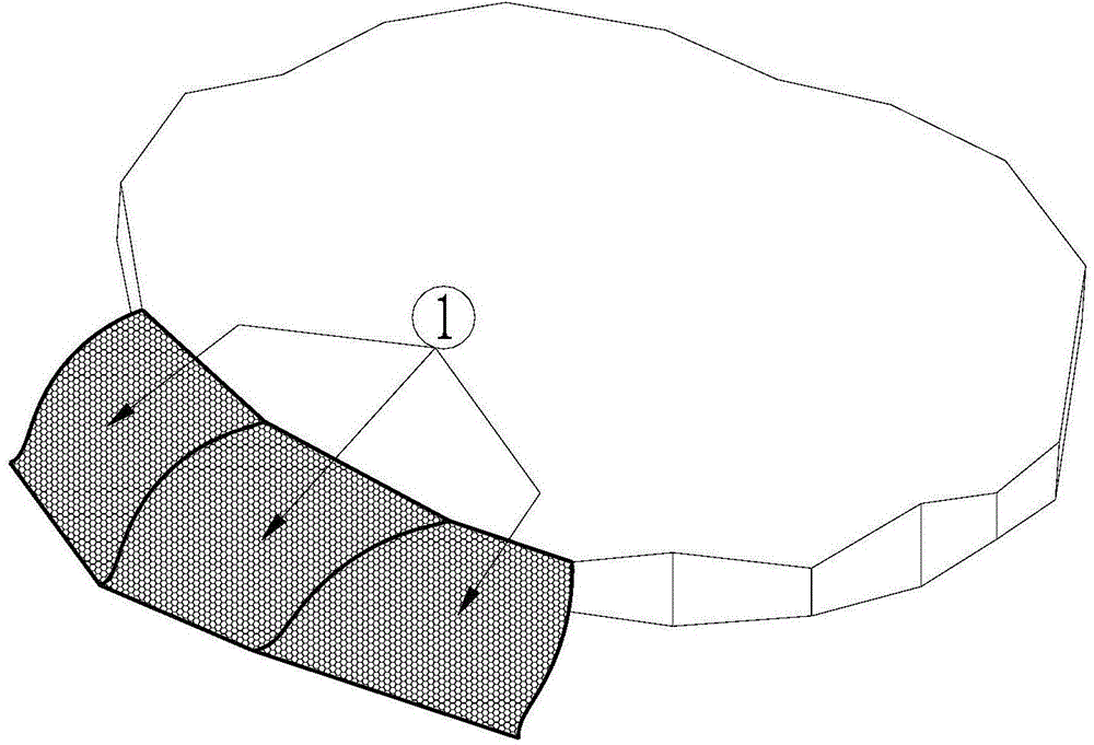
[0032] A three-dimensional gradual boundary transition device applied to wind tunnel tests of wind field characteristics of terrain models, such as Figure 1 ~ Figure 2 As shown, the transition device is spliced ​​by a plurality of segments 1, wherein the specific composition of each segment 1 is:

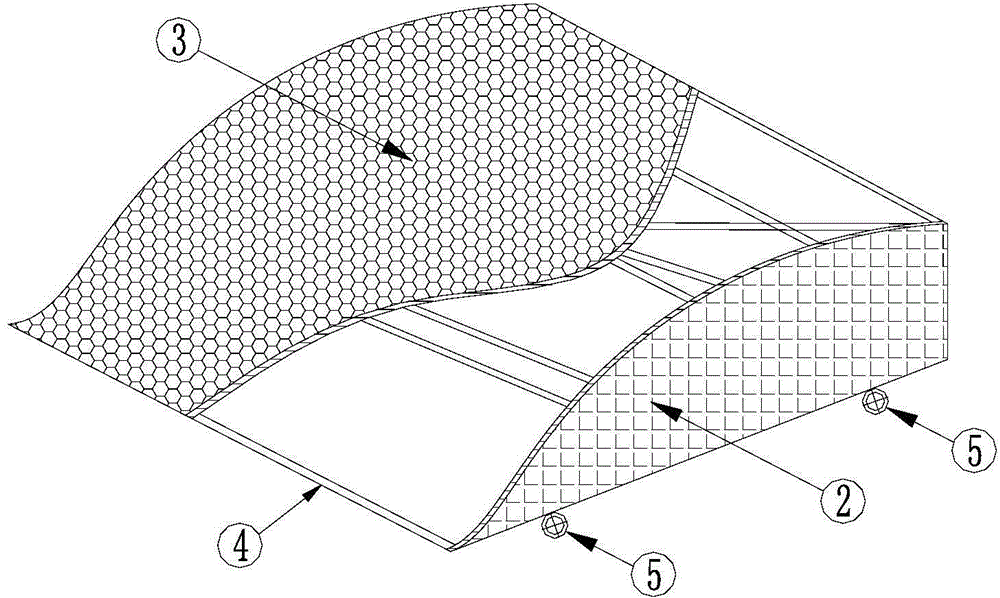
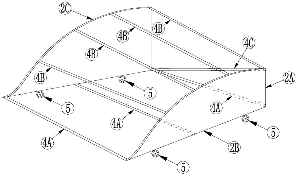
[0033] The three sides of each side panel 2 are vertical side 2A, bottom side 2B and curved side 2C; the bottom sides 2B of the two side panels 2 erected are connected by 3 to 5 lower horizontal braces 4A; the two side panels 2 The curved side 2C of the side plate 2 is connected by 4 to 6 upper cross braces 4B, and the end points of the 4 to 6 upper cross braces 4B are evenly distributed on the curved side 2C of the side plate 2; The bottom end of the vertical side 2A of the board 2 is connected by a diagonal brace 4C; the surface layer 3 of the KT board is fixedly laid on the curved surface formed by the curved side 2C of the two side boards 2 and the upper cross brace 4B.

[003...


PUM


Abstract

The invention discloses a three-dimensional gradient boundary transition device applied to wind field characteristic wind tunnel experiments of a terrain model. the boundary transition device is mainly formed by serially connecting and splicing a plurality of sections; each section comprises two side plates and a surface layer; each side plate comprises a vertical edge, a bottom edge and a curve edge; the surface layer is fixedly paved on the curve edges of two corresponding side plates; the vertical edges of the side plates are higher than positions corresponding to the boundaries of the terrain model; the lengths of the bottom edges of the side plates are 5 to 8 % of the width of a wind tunnel; the gradient between the vertical edge of each side plate and the bottom edge of the side plate is 20 to 40 degrees; the line font of the curve edge of each side plate is defined according to the equation that y-r<2>/y+r<2>x<2>/y<3>-r<2>x<4>/y<5>+r<2>x<6>/y<7>-r<2>x<8>/y<9>-m=0, wherein x represents the radial position of each curve edge, y represents the vertical position of the curve edge, the parameters r and m are defined according to the equation set shown in the specification, h0 represents the height of each vertical edge, k0 represents the ratio between the height of the vertical edge and the length of each bottom edge. Through the adoption of the boundary transition device, under the premise that a wind field characteristic meets requirements after airflow transition, the requirement of wind tunnel space is low, and the applicability is high.

Description

technical field [0001] The invention relates to a three-dimensional gradually changing boundary transition device applied to wind tunnel tests of wind field characteristics of terrain models. Background technique [0002] To build a bridge in a mountainous area with complex terrain, it is necessary to obtain the wind characteristic parameters such as the average wind speed and fluctuating wind speed in the bridge site area through the wind tunnel test of the bridge site area model, so as to provide a scientific basis for the wind resistance design and construction of the bridge. In addition, when the macro and micro sites of wind farms are selected in complex mountainous terrain, the wind field parameters at the wind farm site must also be clarified, so as to provide guarantee for the efficient and safe operation of wind turbines. In the wind tunnel test of the wind field characteristics of the terrain model, due to the limitation of the size of the wind tunnel test section,...

Claims


Application Information

Patent Timeline
IPC IPC(8): G01M9/04
Inventor 胡朋李永乐韩艳武兵王云飞魏恩来
Owner SOUTHWEST JIAOTONG UNIV
Why Eureka
Try Eureka