Sun-tracking photovoltaic power generation device

A power generation device and solar photovoltaic technology, applied in photovoltaic power generation, photovoltaic modules, photovoltaic module support structures, etc., can solve problems such as gear wear, gear or tray or support damage, increase service life, avoid easy wear and tear and Damage, ability-enhancing effect

Inactive Publication Date: 2016-09-07
吴宣湖
View PDF4 Cites 0 Cited by
  • Summary
  • Abstract
  • Description
  • Claims
  • Application Information

AI Technical Summary

Problems solved by technology

When the sun-tracking photovoltaic power generation device is used on a plateau with strong winds or an island with frequent typhoons, the large-area tray will bear strong wind force, and this force will be transmitted to various gears through the cross turning mechanism. The gears are severely worn, and the gears or trays or supports are damaged in severe cases

Method used


Image

  • Sun-tracking photovoltaic power generation device
  • Sun-tracking photovoltaic power generation device
  • Sun-tracking photovoltaic power generation device

Examples


Embodiment 1

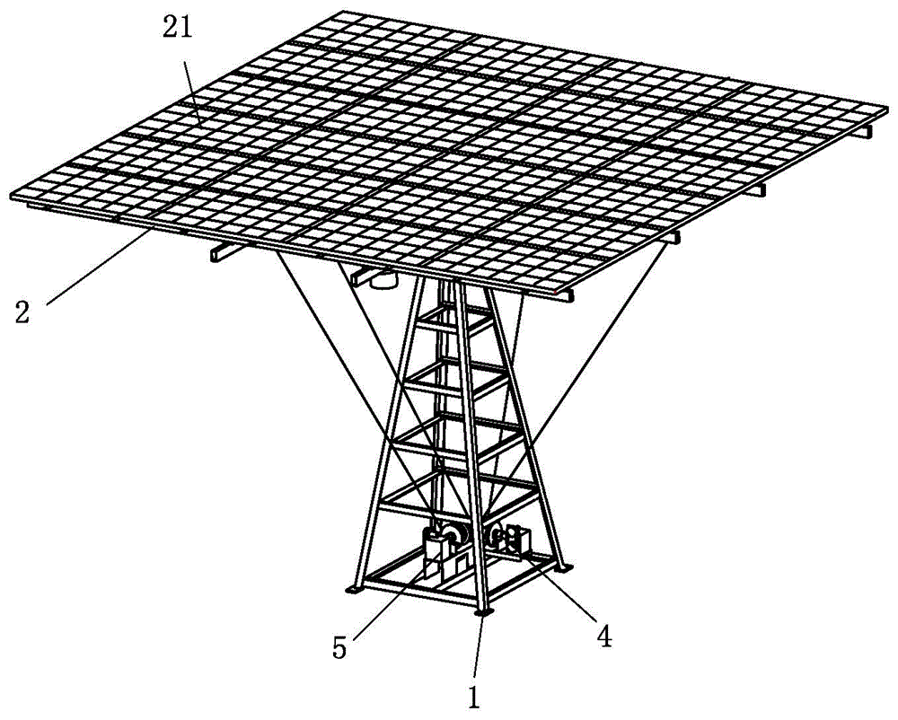
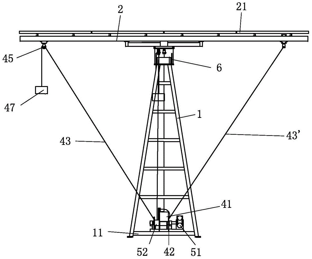
[0028] The structure of an embodiment of the solar tracking photovoltaic power generation device of the present invention, such as figure 1 , figure 2 and image 3 shown. It has an upright support 1, a rectangular tray 2 carrying a solar power generation device array 21, a pitch swing mechanism 4, a main swing mechanism 5, a cross turning mechanism 6, and an intelligent controller.

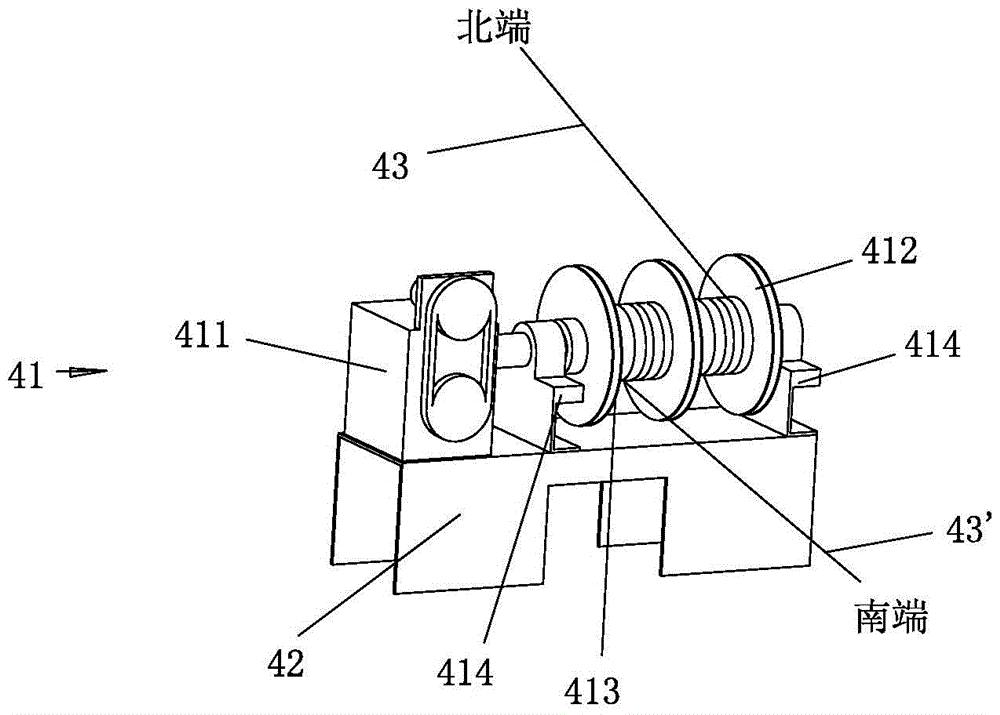
[0029] The support 1 is a square cone-shaped frame welded by angle steel. The cross turning mechanism 6 is fixed on the upper end of the support 1 and is reversibly connected to the middle of the tray 2 . A wide channel steel is welded on the lower connecting frame at the bottom of the support 1, and the auxiliary winch 41 of the pitching and swinging mechanism 4 is installed in the middle of the wide channel steel, and the main hoisting machine 51 of the main swinging mechanism 5 is installed on the east side of the wide channel steel . Of course, the support 1 can also adopt an octagonal ta...

Embodiment 2

[0045] The second embodiment of the sun-tracking photovoltaic power generation device of the present invention is an improvement on the previous embodiment, which can provide stronger wind resistance. Its three-dimensional structure, such as Figure 5 shown. It has an upright support 10, a rectangular tray 2 carrying a solar power generation device array 21, a pitch swing mechanism 40, a main swing mechanism 50, a cross turning mechanism 6, and an intelligent controller. The tray 2 is provided with a plurality of cross beams and longitudinal beams parallel to its edges, as well as cross bars and longitudinal bars required for installing solar power generation devices.

[0046] The support 10 is a square cone-shaped frame welded by angle steel. The cross turning mechanism 6 is fixed on the upper end of the support 1 and connected to the middle of the tray 2 reversibly. Please see Figure 5-1 A wide channel steel is welded on the lower connection frame 101 at the bottom of th...


PUM


Abstract

The invention provides a sun-tracking photovoltaic power generation device, and relates to solar power generation equipment. The device comprises a support, a crossed turning mechanism, a main swing mechanism, a pitch swing mechanism and a rectangular tray bearing a solar power generation device array, wherein the crossed turning mechanism is fixed at the upper end of the support and can be connected with the center point of the tray in a biaxially swinging manner; the main swing mechanism winds or unwinds eastern and western steel cables through a main winch, the steel cables are connected with the middles of the eastern and western edges of the tray, so that the tray can swing eastwards and westwards, a main heavy punch and a main upper pulley are arranged at the upper end of the western steel cable or the eastern steel cable, and the main heavy punch is used for balancing the length difference of upward extension parts of the western and eastern steel cables when the tray swings eastward and westward; the pitch swing mechanism winds or unwinds southern and northern steel cables through an auxiliary winch, the southern and northern steel cables are connected with the middles of the southern and northern edges of the tray, then the tray can perform pitch swinging, an auxiliary heavy punch and an auxiliary upper pulley are arranged at the upper end of the southern or northern steel cable, and the auxiliary heavy punch is used for balancing the length difference of upward extension parts of the southern and northern steel cables when the tray performs pitch swinging. The anti-wind capacity can be improved.

Description

technical field [0001] The invention relates to a solar power generation device. Background technique [0002] Existing solar power generation equipment is divided into two types: fixed type and reversible type. Fixed solar power generation equipment is to set solar power generation devices (commonly known as photovoltaic cells) on a fixed carrier; when in use, the angle of sunlight shining on the solar power generation devices changes with time, and the electric energy generated by the unit energy of solar energy (that is, power generation efficiency) It also varies with the time of day at different times. When the sun's rays irradiate the surface of the solar power generation device vertically (such as at noon), the electric energy generated by the solar energy per unit of energy is the strongest (that is, the power generation efficiency is the highest). The greater the inclination angle of the sun's rays irradiating the surface of the solar power generation device, the ...

Claims


Application Information

Patent Timeline
Patent Type & Authority Patents(China)
IPC IPC(8): H02S20/32
CPCH02S20/00Y02E10/50
Inventor 吴宣湖
Owner 吴宣湖
Why Eureka
Try Eureka