Exhaust gas system with thermoelectric generator

A technology of thermoelectric generators and exhaust devices, which is applied in the direction of exhaust devices, exhaust treatment, noise reduction devices, etc., and can solve problems such as material damage

Active Publication Date: 2015-05-27
BAYERISCHE MOTOREN WERKE AG
View PDF7 Cites 1 Cited by
  • Summary
  • Abstract
  • Description
  • Claims
  • Application Information

AI Technical Summary

Problems solved by technology

A third overload situation occurs when the permissible maximum temperature of the thermoelectric material of the thermoelectric generator is exceeded, whereby the material may be damaged

Method used


Image

  • Exhaust gas system with thermoelectric generator
  • Exhaust gas system with thermoelectric generator
  • Exhaust gas system with thermoelectric generator

Examples


Embodiment Construction

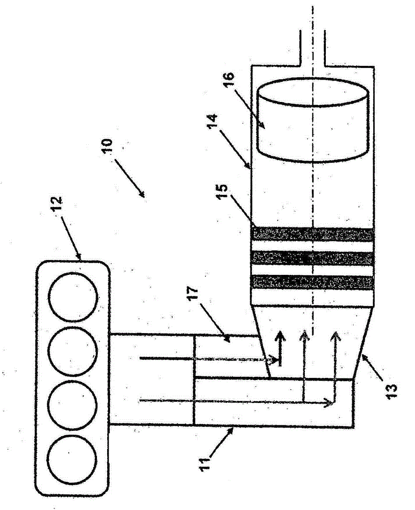
[0031] exist figure 1 An exhaust device 10 according to the prior art is shown in . The exhaust system 10 includes an exhaust pipe 11 with an elbow (manifold) 12 which can be connected, for example, to an internal combustion engine of a motor vehicle (not shown) for the purpose of discharging the exhaust gas. In addition, the exhaust gas pipe 11 comprises an exhaust gas turbocharger with a turbine 13 and a downstream flame pipe 14 with an integrated thermoelectric generator 15 and an exhaust gas catalytic converter arranged behind it in the flow direction. 16. The exhaust gas catalytic converter is designed as an axial catalytic converter, for example. Furthermore, the exhaust device 10 can be divided into a hot side (“Hot end”) and a cold side (“Cold End”), wherein the “Hot end” includes the following components: exhaust pipe 11 , elbow 12 , turbine 13 and bypass pipe 17. In this case, the "Cold End" includes the following components: the flame tube 14 and the exhaust gas ...


PUM


Abstract

The invention relates to an exhaust gas system (20), in particular for an internal combustion engine (22), comprising an exhaust gas line (21). The exhaust gas line (21) comprises at least one turbocharger (23) and a thermoelectric converter arrangement (24) which is arranged downstream of the turbocharger in the flow direction (S) of an exhaust gas and which comprises a thermoelectric converter stage (25). The exhaust gas line (21) is paired with at least one bypass line (27) which branches out from the exhaust gas line (2) upstream of the turbocharger (23) in an exhaust gas-conductive manner in order to discharge at least one part (B) of the exhaust gas into the at least one bypass line (27), said at least one bypass line (27) opening into the exhaust gas line (21) downstream of the thermoelectric converter stage (25) in an exhaust gas-conductive manner.

Description

technical field [0001] The invention relates to an exhaust device according to the preamble of claim 1 . Background technique [0002] For example, the exhaust gas of an internal combustion engine of a motor vehicle usually has a high thermal energy. In order to utilize this thermal energy and avoid its unutilized discharge into the environment, exhaust devices are known which comprise a thermoelectric conversion arrangement for exhaust gas energy recovery. Such an exhaust system can significantly increase the overall energy efficiency of the internal combustion engine through partial energy recovery. [0003] Thermoelectric generators are used in this case, which are known to be integrated in exhaust gas catalysts and comprise thermoelectric transducer elements which convert thermal energy into electrical energy based on the well-known "Seebeck effect". In short, the temperature difference between the two ends of the transducer element, which in the case of motor vehicles...

Claims


Application Information

Patent Timeline
Patent Type & Authority Applications(China)
IPC IPC(8): F01N5/02F02B37/18
CPCF01N5/025F01N2240/36F01N2410/02F01N2410/10F02B37/18Y02T10/12
Inventor A·鲍克内希特S·布彻尔
Owner BAYERISCHE MOTOREN WERKE AG
Why Eureka
Try Eureka