Actuating unit for variable power plant components

An engine and component technology, applied in the direction of engine control, machine/engine, mechanical equipment, etc., to achieve the effect of simplifying processing, simplifying the control unit, and reducing the structure space

Active Publication Date: 2015-05-27
FEV 有限责任公司
View PDF8 Cites 9 Cited by
  • Summary
  • Abstract
  • Description
  • Claims
  • Application Information

AI Technical Summary

Problems solved by technology

[0009] This form of manipulation has drawbacks and also requires relatively large changes to already existing motors, especially on the cylinder crankcase

Method used


Image

  • Actuating unit for variable power plant components
  • Actuating unit for variable power plant components
  • Actuating unit for variable power plant components

Examples


Embodiment Construction

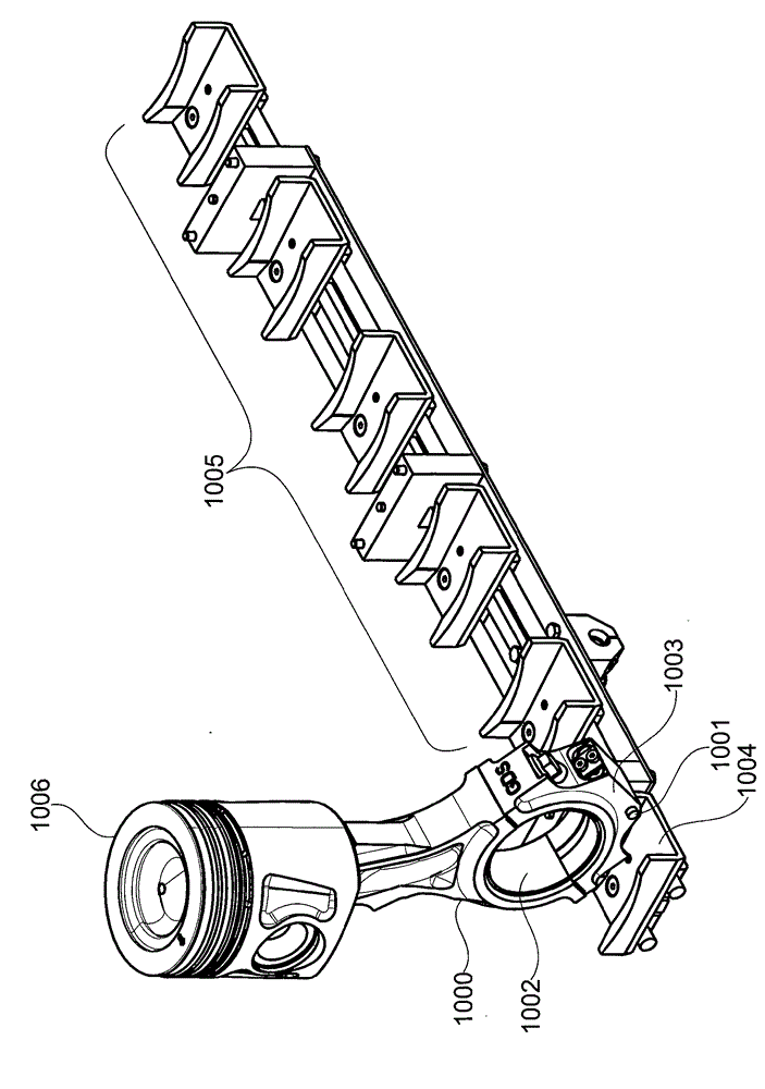
[0044] figure 1 A connecting rod 1000 is shown in which a switching element 1001 is arranged on a large connecting rod bore 1002 . The adjustment device for adjusting the adjustable and variable compression ratio is provided on the small connecting rod hole of the connecting rod 1000 . This adjustment device is figure 1 The center is covered by the piston 1006. In particular, the switching element 1001 can be integrated into the connecting rod cover 1003 . Furthermore, a cam element 1004 for actuating the switching element 1001 can be arranged below the crankshaft of the reciprocating-piston internal combustion engine. In particular, a cam element is provided for each connecting rod of a cylinder of a reciprocating piston internal combustion engine. Each cam member of each cylinder preferably constitutes a pre-assembled module 1005 . exist figure 1 The module shown in 1005 is for a 6-cylinder in-line engine.

[0045] figure 2 A hydraulic directional valve 1010 for ...


PUM


Abstract

The invention relates to a reciprocating-piston internal combustion engine with variable compression, having an actuating unit for changing a variable compression of the reciprocating-piston internal combustion engine, wherein, to change the variable compression, the actuating unit actuates a variable power plant component of the reciprocating piston internal combustion engine in the form of a connecting rod with a variable length, a piston with a variable compression height and / or a crankshaft with a variable crankshaft radius, and the actuating unit is arranged in a lower region of the reciprocating-piston internal combustion engine. Also proposed are a method and also an actuating unit for the same.

Description

technical field [0001] The invention relates to a reciprocating piston internal combustion engine with variable compression via an operating unit for varying the compression of a reciprocating piston internal combustion engine, and also to an operating unit preferably for the proposed reciprocating piston engine and an adapted reciprocating Method of variable compression for piston internal combustion engines. It is suggested here that different variations of engine components can be utilized, namely: [0002] Connecting rods with varying lengths [0003] Pistons with varying compression heights [0004] Crankshaft with varying crankshaft radius [0005] All of these components are especially aimed at achieving variable compression. Background technique [0006] The modified engine parts described in more detail below differ from eccentrically adjusted crankshafts, such as those given by DE 100 08 423 A1, in that they are moving parts of the drive, but themselves undergo...

Claims


Application Information

Patent Timeline
Patent Type & Authority Applications(China)
IPC IPC(8): F02B75/04F02D15/02
CPCF02B75/045F02B75/04F02B75/243F16C7/06Y10T29/49233F02D15/02F02B75/044F02B75/047F02D2700/03
Inventor K.维特克
Owner FEV 有限责任公司
Why Eureka
Try Eureka