Catheter drainage tube

A drainage tube and catheterization technology, which is applied in the field of urinary catheterization and drainage tubes, can solve problems such as blockage of catheterization and drainage tubes, time-consuming and laborious, difficult operation, etc., and achieve the effect of easy acceptance, simple and quick operation, and less pain for patients

Inactive Publication Date: 2015-06-03
王兆华
View PDF10 Cites 7 Cited by
  • Summary
  • Abstract
  • Description
  • Claims
  • Application Information

AI Technical Summary

Problems solved by technology

[0005] However, in actual clinical use, even if the patient's body is continuously dripped with physiological saline for flushing, there will still be formed elements such as blood clots, which will cause the blockage of the cathe

Method used


Image

  • Catheter drainage tube
  • Catheter drainage tube
  • Catheter drainage tube

Examples


Embodiment Construction

[0026] The present invention will be further described below in conjunction with accompanying drawing and specific embodiment:

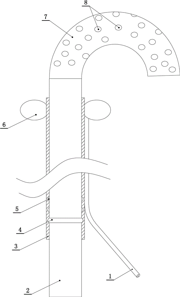
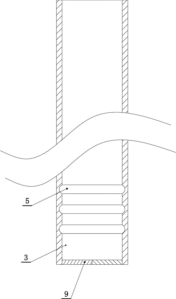
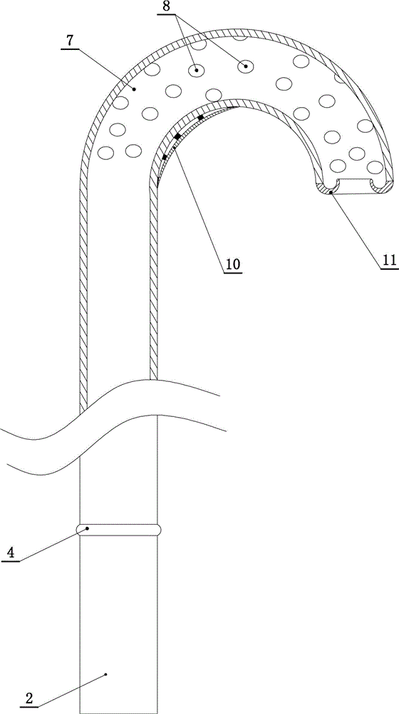
[0027] A urinary catheter, such as figure 1 shown, including urinary drainage set 3 (see figure 2 ), the urinary catheterization and drainage core tube 2 that can be relatively inserted and removed is worn in the catheterization and drainage tube sleeve 3 (see image 3 ). The proximal end of the urinary catheterization and drainage core tube 2 is in a "C"-shaped 7 structure in a natural state. When the proximal end of the urinary catheterization and drainage core tube 2 penetrates into the urine drainage tube sleeve 3, the proximal end of the urinary catheterization and drainage core tube 2 The end is straightened, and when the proximal end of the catheterization and drainage core tube 2 stretches out from the proximal end of the urinary drainage tube cover 3, it will automatically bend into a "C" shape. The inner side of the outer wall of the "C...


PUM

PropertyMeasurementUnit
Arc radiusaaaaaaaaaa

Abstract

The invention discloses a catheter drainage tube, which comprises a catheter drainage tube sleeve, wherein a catheter drainage core tube which can be relatively plugged is arranged in the catheter drainage tube sleeve in a penetrating manner; the near end of the catheter drainage core tube is in a C-shaped structure in a natural state; the inner side of the outer lateral wall of a C-shaped segment at the near end of the catheter drainage core tube is integrally connected with a stretch-bending rib along the trend of the catheter drainage core tube; a groove is formed in the inner lateral wall of the far end of the catheter drainage tube sleeve; the outer lateral wall of the far end of the catheter drainage core tube is integrally connected with a ring buckle; after the catheter drainage core tube is inserted into the catheter drainage tube sleeve, the ring buckle is buckled into the groove; the stretch-bending rib is in an arc form in a natural state; the arc radius of the stretch-bending rib in a natural state is M; the arc radius of the C-shaped segment at the near end of the catheter drainage core tube in the natural state is N; M is smaller than N; the stretch-bending rib and the C-shaped segment at the near end of the catheter drainage core tube are in discontinuous point-contact intermittent connection; and an opening at the near end of the catheter drainage core tube is integrally connected with a turned edge which crimps inwards.

Description

technical field [0001] The invention relates to a medical device, in particular to a urinary catheterization and drainage tube. Background technique [0002] At present, common urinary catheters and drainage tubes are generally made of natural rubber, silicone rubber or polyvinyl chloride (PVC). The main purpose is to insert the bladder through the urethra to drain urine. After inflation, it expands into a spherical shape and is used to fix the catheter and drainage tube so that its proximal end stays in the bladder to prevent slippage. The distal end of the catheter and drainage tube is connected to a urine bag for collecting urine. [0003] However, for patients with bladder tumors or renal ureteral bleeding, there are often formed elements such as blood clots in the body, which can cause blockage of the catheter drainage tube. [0004] In order to alleviate the blockage of the drainage tube, an irrigation channel is added to the above-mentioned urinary catheter drainage ...

Claims


Application Information

Patent Timeline
IPC IPC(8): A61M25/14
Inventor 王兆华王晓晨
Owner 王兆华
Why Eureka
Try Eureka