
Revolving table device

A technology of rotating worktable and rotating platform, applied in manufacturing tools, metal processing equipment, metal processing machinery parts, etc., can solve the problems of inconvenient maintenance, reducing the service life of various components, affecting processing accuracy, etc.

Inactive Publication Date: 2015-06-03
HIPRO PRECISION
View PDF9 Cites 6 Cited by
  • Summary
  • Abstract
  • Description
  • Claims
  • Application Information

AI Technical Summary

Problems solved by technology

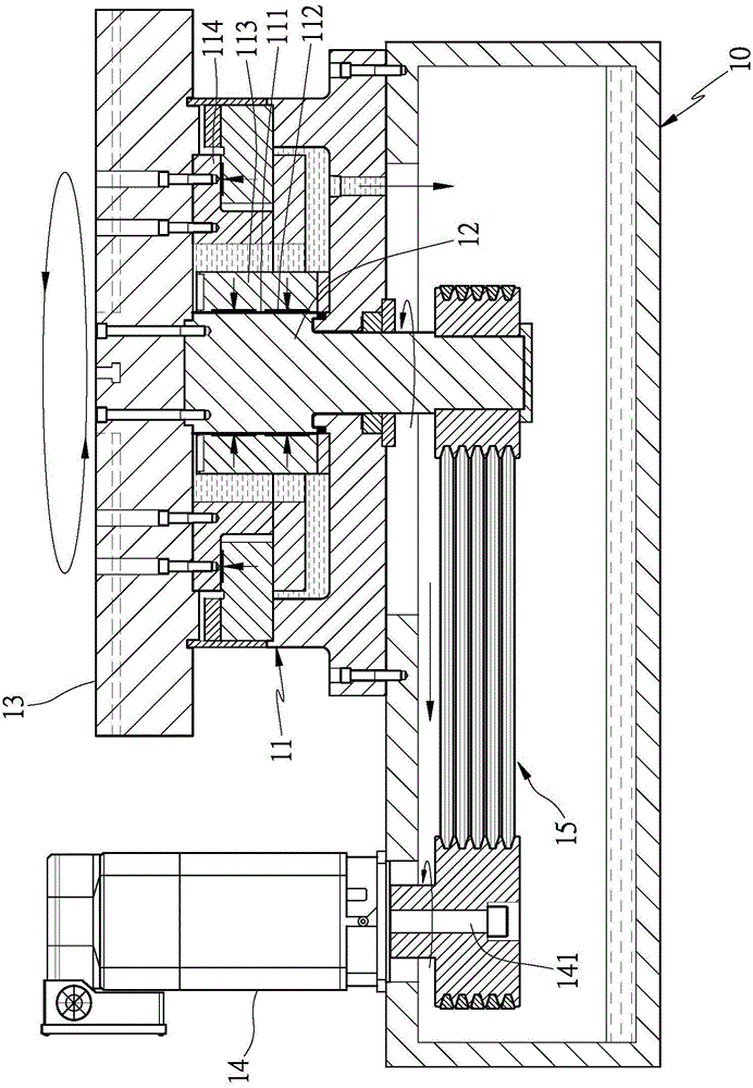
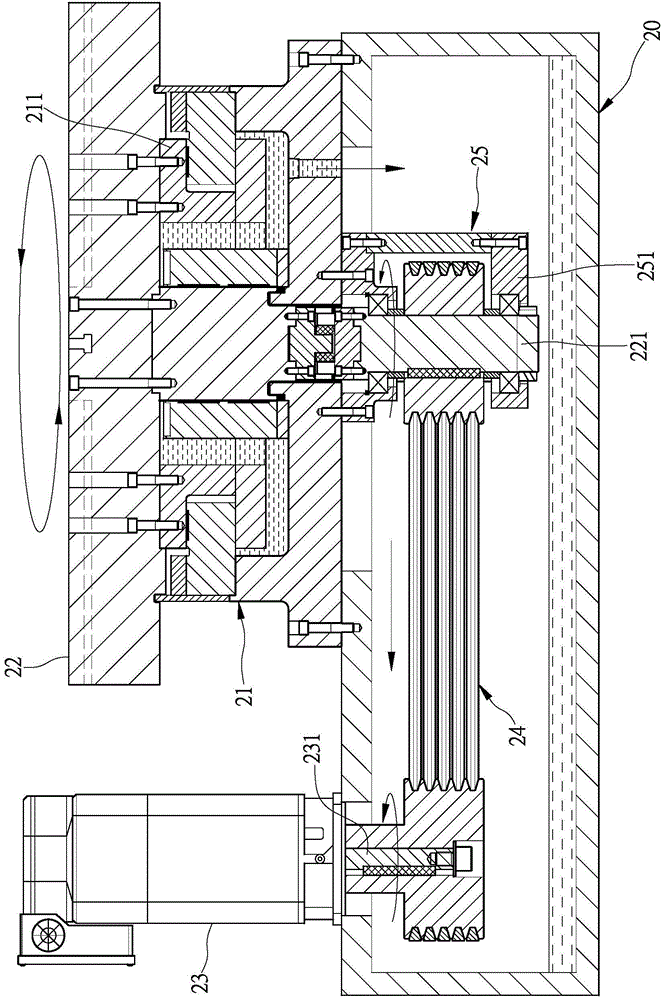
[0007] 1. Since the bearing plate 251 of the bracket group 25 is supported on the end of the rotating shaft 221, the pulley of the pulley group 24 is located in the frame of the bracket group 25. When the pulley or the belt must be replaced and repaired due to wear and tear, It is necessary to remove the hydrostatic bearing 21 first, and then remove the frame group 26 to take out the pulley or the belt for replacement and maintenance, which causes great inconvenience in maintenance.
[0008] 2. When the motor 23 rotates for a long time, the high heat generated by it will be transmitted to the machine base 20, the hydrostatic bearing 21 and the rotating shaft 221, causing thermal deformation of each component, which not only affects the machining accuracy, but also easily reduces Service life of each component

Method used


Image

  • Revolving table device
  • Revolving table device
  • Revolving table device

Examples


Embodiment Construction

[0040] In order to make your review committee members have a further understanding of the present invention, the preferred embodiments are hereby given in conjunction with the drawings, and are described in detail as follows:

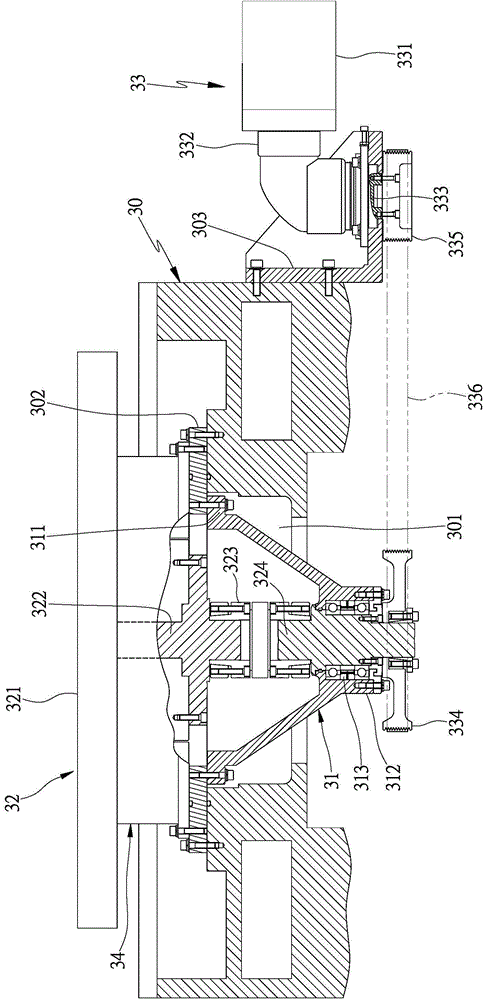
[0041] see image 3 The rotary table device of the present invention mainly includes a pedestal 30, a support ring body 31, a rotary platform 32 and a rotary drive mechanism 33. The pedestal 30 is a body, and a space 301 is provided inside for mounting the rotary platform. 32. An inverted cone-shaped support ring 31 is fixed in the insertion space 301 of the pedestal 30. In this embodiment, the large-diameter end above the support ring 31 has a connecting seat 311, and the small-diameter end below is There is a support seat 312 for installing a bearing group 313, and the support ring body 31 is locked and connected to the pedestal 30 above with the connection seat 311. In this embodiment, the pedestal 30 is first locked with the connecting plate 302, an...


PUM


Abstract

The invention provides a revolving table device, mainly comprising a pedestal, a support ring body, a revolving platform and a revolving driving mechanism, the pedestal is fixedly equipped with an inverted cone-shaped support ring body at a lower position, the support ring body is equipped with a support seat for assembling a bearing pack at a lower end, the revolving platform of a revolving shaft is pivoted on the pedestal, the revolving shaft of the revolving table downward passes through the support seat of the support ring body in a sleeved manner, and makes the shaft end of the revolving shaft downward stretch out of the support seat in a protruded manner, the revolving driving mechanism is equipped with a driving source on one side of the pedestal, a transmission set is arranged between the output shaft of the driving source and the shaft end of the revolving shaft of the revolving platform, and can drive the revolving platform to revolve on the pedestal when the driving source actuates; therefore, not only can the support ring body be used to prevent the revolving shaft of the revolving platform from generating side direction deviation, but also the transmission set of the revolving driving mechanism is arranged below the support ring body, so as to be convenient for conducting maintenance operation, and then the practical benefits that the machining precision is guaranteed and the maintenance is easy are achieved.

Description

technical field [0001] The invention relates to a rotary table device which is applied in the field of workpiece processing and can ensure processing accuracy and is easy to maintain. Background technique [0002] The rotary table is widely used in metal processing machinery. In terms of inner hole or outer cylindrical grinding of today's precision grinding machines, the rotary table is used to support the workpiece, and the workpiece is rotated by the grinding tool. Grinding of inner hole or outer circle. Rotary workbenches have been developed to use hydrostatic bearings today, which mainly use the hydraulic system to supply hydraulic oil to the oil chamber of the shaft hole of the hydrostatic bearing, so that an oil film is formed between the rotating shaft and the shaft hole of the hydrostatic bearing. The rotating shaft rotates under the coating lubrication of hydraulic oil, which has the advantages of high precision, low vibration, low wear and long service life. The ...

Claims


Application Information

Patent Timeline
IPC IPC(8): B23Q1/26B23Q1/44
CPCB23Q1/26B23Q1/44
Inventor 陈泳霖
Owner HIPRO PRECISION
Learn More