
Car headlamp reflector die

A reflective mirror and concave mold technology, applied in metal processing equipment, forming tools, manufacturing tools, etc., can solve problems such as thinning, insufficient effective control of material flow, inaccurate focusing of reflective mirrors, etc., to achieve improved tearing, Height adjustment is convenient and quick

Inactive Publication Date: 2015-06-03
TIANJIN XINRI ELECTROMECHANICAL
View PDF0 Cites 0 Cited by
  • Summary
  • Abstract
  • Description
  • Claims
  • Application Information

AI Technical Summary

Problems solved by technology

[0003] The depth of the drawing bead is an important parameter to adjust the flow resistance. The drawing bead is arranged on the side of the pressing plate. If the depth of the drawing bead is too shallow, it is not enough to effectively control the material flow. There are problems such as cracking and thinning, and the theoretically calculated height value of the deep drawing bead of the die deviates from the actual working condition. The effect of deep ribs on improving wrinkling or cracking is reduced, which may cause inaccurate light collection and random reflection of astigmatism in the reflector

Method used


Image

  • Car headlamp reflector die

Examples


Embodiment 1

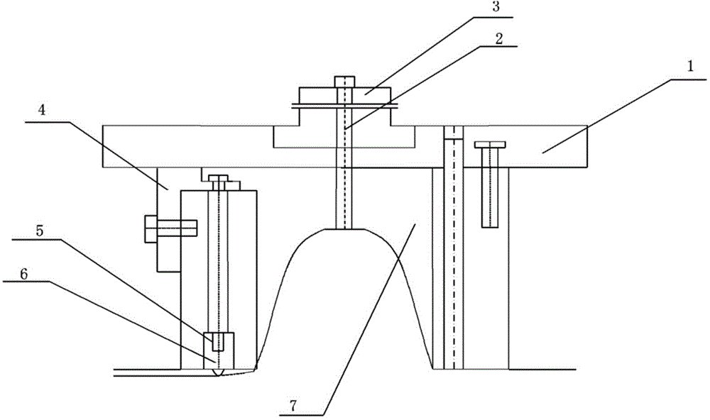
[0013] The electric vehicle headlight reflector die includes a die main body 7, an upper template 1, a handle 3, a feeder 2 and a drawbead assembly, and the drawbead assembly includes a drawbead 6 and a drawbead The positioner 4 and the adjusting spacer 5, the drawbead positioner 4 placed on the lower side of the upper template 1 positions one end of the drawbead 6, and the other end of the drawbead 6 is adjusted in height through the adjustment spacer 5.

[0014] The beater 2 and the mold handle 3 are fixedly installed in the middle of the upper template 1 .

[0015] The thickness of the drawn rib 6 is 7mm, and the length is 30mm. The drawn height is 3mm, and then the spacer 4 is adjusted according to the actual situation of the electric vehicle headlight.

[0016] In the process of adjusting the height of the drawbead 6, only need to take down the drawbead positioner 4, and then take out the drawbead 6, without disassembling the whole mold, the thickness of the adjusting gas...

Embodiment 2

[0019] The electric vehicle headlight reflector die includes a die main body 7, an upper template 1, a handle 3, a feeder 2 and a drawbead assembly, and the drawbead assembly includes a drawbead 6 and a drawbead The positioner 4 and the adjusting spacer 5, the drawbead positioner 4 placed on the lower side of the upper template 1 positions one end of the drawbead 6, and the other end of the drawbead 6 is adjusted in height through the adjustment spacer 5.

[0020] The beater 2 and the mold handle 3 are fixedly installed in the middle of the upper template 1 .

[0021] The thickness of the drawn rib 6 is 10mm, and the length is 45mm. The drawn height is 5mm, and then the spacer 4 is adjusted according to the actual situation of the electric vehicle headlight.

[0022] In the process of adjusting the height of the drawbead 6, only need to take down the drawbead positioner 4, and then take out the drawbead 6, without disassembling the whole mold, the thickness of the adjusting ga...


PUM

PropertyMeasurementUnit
lengthaaaaaaaaaa
thicknessaaaaaaaaaa
lengthaaaaaaaaaa

Abstract

The invention discloses a car headlamp reflector die. The reflector die comprises a main die body, an upper template, a die shank, a feeder and a draw bead assembly, wherein the draw bead assembly comprises a draw bead, a draw bead locator and an adjusting shim; one end of the draw bead is located by the draw bead locator on the lower side of the upper template and the other end of the draw bead is adjusted in height through the adjusting shim. The feeder and the die shank are fixedly installed at the middle position of the upper template. The car headlamp reflector die is characterized in that the draw bead which can be adjusted in height is arranged in the die, so that the flow resistance of the metal material can be adjusted, the problem of cracking and thinning blanks is improved, the height of the draw bead can be adjusted through the adjusting shim to make up for the deviation between the theoretical arithmetic height value and the actual operation condition of the draw bead, and the height of the draw bead can be conveniently and quickly adjusted in a adjusting process.

Description

technical field [0001] The invention relates to a concave mold of a vehicle headlamp reflector. Background technique [0002] The reflector of a car headlight is a box-shaped symmetrical part with a flange. Since the reflector presents a parabolic surface, the quality of its surface directly affects the convergence and dispersion of the light. Therefore, the optical parameters of the workpiece are very high, and the shape of the surface must be strictly guaranteed. The accuracy, the manufacturing process is generally blanking, deep drawing, edge trimming and punching, because the flow velocity of different parts of the material in the deep drawing process is not the same, the flow velocity of the four corners symmetrically distributed in the box shape is obviously smaller than that of The central part of the four sides, therefore, the corners are easy to crack, and the four sides are easy to wrinkle. In order to avoid possible wrinkling or cracking during the forming process...

Claims


Application Information

Patent Timeline
Patent Type & Authority Applications(China)
IPC IPC(8): B29C33/00B21D37/10
Inventor 刘小东
Owner TIANJIN XINRI ELECTROMECHANICAL
Learn More