
Cooling device for air duct cloth

The technology of cooling device and air duct cloth is applied in the field of air duct cloth production device, which can solve the problems of uneven cooling and low efficiency of air duct cloth, and achieve the effects of improving cooling effect, convenient operation and high cooling efficiency.

Active Publication Date: 2016-10-05
成都众成新型复合材料有限公司
View PDF6 Cites 0 Cited by
  • Summary
  • Abstract
  • Description
  • Claims
  • Application Information

AI Technical Summary

Problems solved by technology

[0003] The purpose of the present invention is to provide a cooling device for the fan cloth in view of the problems in the prior art that the traditional fan cloth is sprayed with water, resulting in uneven cooling and low efficiency of the fan cloth. Design several groups of rollers crossing horizontally and vertically. Each roller group has flowing water passing through it. When the air duct cloth passes through the roller group, all the rollers will cool the air duct cloth body, which can not only cover all surfaces of the air duct cloth, but also Disposable cooling air duct cloth, the air duct cloth cools evenly, and the cooling efficiency is high, and the operation is convenient

Method used

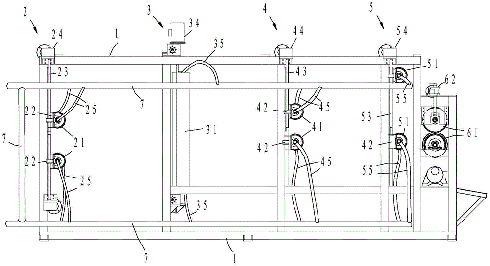
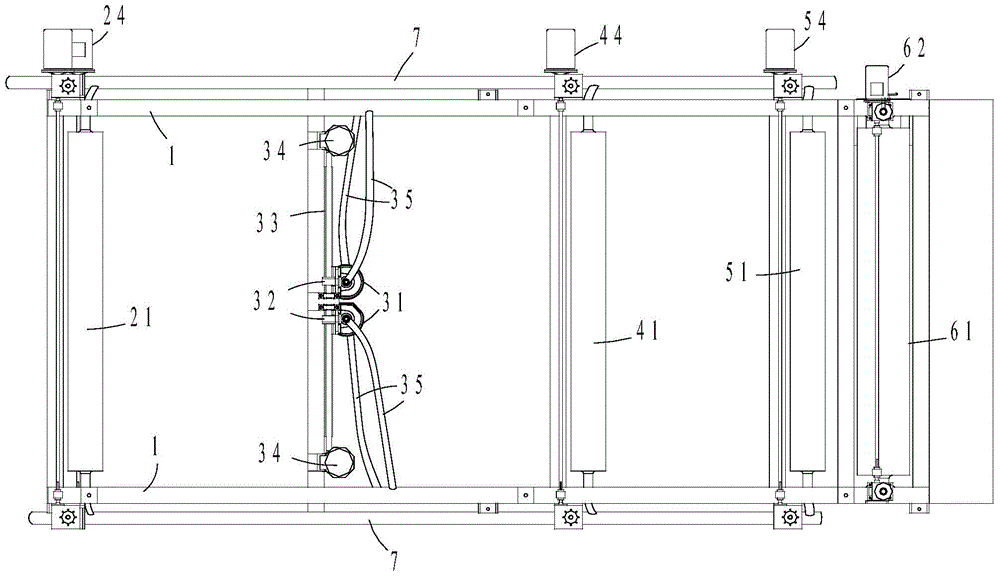
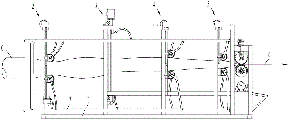

Image

  • Cooling device for air duct cloth
  • Cooling device for air duct cloth
  • Cooling device for air duct cloth

Examples


Embodiment Construction

[0033] Below in conjunction with accompanying drawing, the present invention is described in detail.

[0034] In order to make the object, technical solution and advantages of the present invention clearer, the present invention will be further described in detail below in conjunction with the accompanying drawings and embodiments. It should be understood that the specific embodiments described here are only used to explain the present invention, not to limit the present invention.

[0035] Such as figure 1 , 2As shown, a cooling device for air duct cloth includes a support 1, and the support 1 is provided with four roller groups (2, 3, 4, 5) arranged in the horizontal direction and the vertical direction, respectively the first Roll set 2, second roll set 3, third roll set 4, fourth roll set 5, each roll set (2,3,4,5) comprising two metal rolls (21,31,41,51), Each roller (21,31,41,51) is provided with a through hole (26,36,46,56), and both ends of each roller (21,31,41,51)...


PUM

PropertyMeasurementUnit
thicknessaaaaaaaaaa

Abstract

The invention relates to a cooling device for wind tube cloth. The cooling device comprises a bracket, wherein a plurality of roller groups which are arranged along the horizontal direction and the vertical direction are arranged on the bracket, each roller group comprises two metal rollers with adjustable spacing, a through hole is formed in each roller, two ends of each roller are communicated with flexible pipes, a pipeline capable of introducing flowing water is arranged on the bracket, and the flexible pipes are communicated with the pipeline; the bracket is also provided with two traction rollers, and the traction rollers are driven to rotate in opposite directions by traction roller motors; and an anti-sticking layer sleeves the roller outer wall of each roller group. The cooling device for wind tube cloth provided by the invention adopts a plurality of roller groups positioned in the horizontal direction or the vertical direction, and the rollers are at room temperature by means of flowing water in the rollers, so that the plasticized wind tube cloth can be effectively cooled, the cooling is environmentally friendly and is hygienic, the cooling efficiency is relatively high, the operation is convenient, the cost is relatively low, and the production quality of the wind tube cloth is improved.

Description

technical field [0001] The invention relates to a production device for air duct cloth, in particular to a cooling device for air duct cloth. Background technique [0002] During the production and processing of the blower cloth, the blower cloth is plasticized in the plasticizing box and then exported. Since the temperature in the plasticizing box is as high as 150°C-170°C, the exported blower cloth needs to be cooled to room temperature in time, that is, 15 ℃-35℃, the air duct cloth can achieve the required good technical characteristics, such as high strength, high wear resistance, folding resistance, and long life; the traditional air duct cloth is exported after production and plasticization, and generally uses water to spray directly on the air Cooling is carried out on the tube body of the tube cloth. In this cooling method, due to the inhomogeneity of the water spray itself, the cooling of the fan tube cloth is also uneven. At the same time, the cooling cannot cover ...

Claims


Application Information

Patent Timeline
Patent Type & Authority Patents(China)
IPC IPC(8): B29C35/16
Inventor 古旗高张权赖奎向波
Owner 成都众成新型复合材料有限公司
Learn More