Fluidized bed gas distributor and gasifier
A gas distributor and fluidized bed technology, applied in the direction of granular/powdered fuel gasification, etc., can solve the problems of easy loss of fluidization of large particles, reduced gasification efficiency of gasifier, uneven distribution of flow field in the furnace, etc. Achieve the effect of reducing processing difficulty and operation and maintenance costs, reducing design operation and maintenance costs, and reducing the risk of slagging
- Summary
- Abstract
- Description
- Claims
- Application Information
AI Technical Summary
Problems solved by technology
Method used
Image

Examples
Example Embodiment
[0032] Example 1
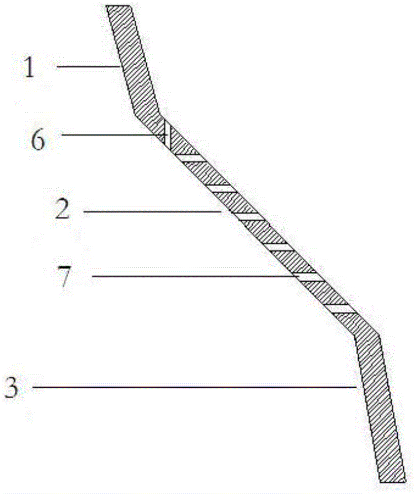
[0033] A fluidized bed gas distributor, such as figure 1 As shown, it includes a fluidization zone, the fluidization zone at least includes a first fluidization zone and a second fluidization zone, the lower end of the first fluidization zone distribution plate 1 is connected to the upper end of the second fluidization zone distribution plate 2, The included angle between the distribution plate 1 of the first fluidized area and the distribution plate 2 of the second fluidized area is at an obtuse angle.
[0034] According to the requirements of different fluidized beds and the properties of raw materials, at least two fluidized zone distribution plates are made to form multiple fluidized zones. Multiple fluidization zone distribution plates can be connected in sequence, or can be connected in other ways according to different requirements. In order to make the material on the first fluidization zone flow into the second fluidization zone smoothly, the ang...
Example Embodiment
[0053] Example 2
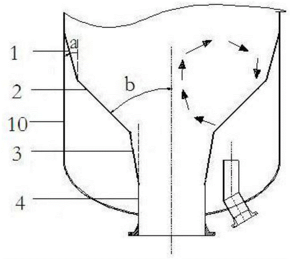
[0054] A gasifier containing a fluidized bed gas distributor, such as figure 2 As shown, the fluidized bed gas distributor is basically the same as that of Example 1, except that:
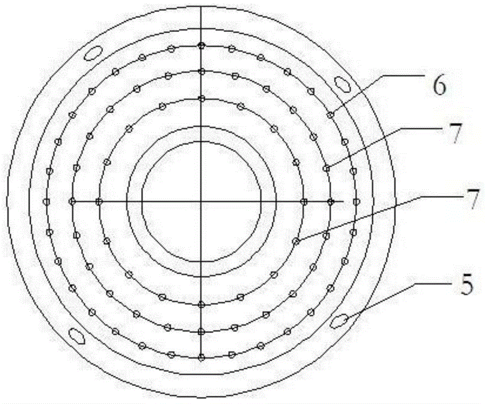
[0055] In this embodiment, the fluidized bed gas distributor has two fluidization zones. like image 3 As shown, the vertical height ratio of the distribution plate 1 in the first fluidized zone and the distribution plate 2 in the second fluidized zone is 1; 0.5%; the swirl holes 5 are placed on the middle annular surface of the distribution plate 1 in the first fluidization zone. like figure 1 As shown, the second fluidization zone distribution plate 2 adopts the form of a folded plate, the angle b between the second fluidization zone distribution plate 2 and the center line of the distributor is 45 degrees, and the small holes of the second fluidization zone distribution plate 2 are The holes are arranged in a combination of vertical and horizontal holes. On the second f...
Example Embodiment
[0069] Example 3
[0070] A gasifier containing a fluidized bed gas distributor, such as Figure 4 As shown, the fluidized bed gas distributor is basically the same as that of Example 2, except that:
[0071] In this embodiment, the vertical height ratio between the distribution plate 1 of the first fluidized zone and the second fluidized zone is 0.2, the distribution plate 1 of the first fluidized zone adopts 6 rotating holes, the diameter of the rotating holes 5 is 4 mm, and the opening rate is 0.6% .
[0072] like Figure 4 As shown, the distribution plate 2 of the second fluidization zone adopts the form of two folded plates, the angle bI between the first folded plate 8 of the second fluidized zone and the center line of the distributor is 31 degrees, and the second folded plate 9 is 31 degrees with the center line of the distributor. The angle bII of the center line of the distributor is 52 degrees, and the small holes of the first folded plate 8 and the second folded...
PUM
| Property | Measurement | Unit |
|---|---|---|
| Particle size | aaaaa | aaaaa |
| Particle size | aaaaa | aaaaa |
Abstract
Description
Claims
Application Information
 - R&D
- Intellectual Property
- Life Sciences
- Materials
- Tech Scout
- Unparalleled Data Quality
- Higher Quality Content
- 60% Fewer Hallucinations
Browse by: Latest US Patents, China's latest patents, Technical Efficacy Thesaurus, Application Domain, Technology Topic, Popular Technical Reports.
© 2025 PatSnap. All rights reserved.Legal|Privacy policy|Modern Slavery Act Transparency Statement|Sitemap|About US| Contact US: help@patsnap.com