A single-sided reciprocating continuous coating magnetron sputtering winding coating machine

A technology of magnetron sputtering and coating machine, which is applied in sputtering coating, ion implantation coating, vacuum evaporation coating, etc. It can solve the problems of inability to sputter three layers of dielectric film continuously, limited number of installations, and many equipments. , to achieve the effect of simplifying the electrical control device and program, facilitating parameter control, and simple and convenient operation

Active Publication Date: 2017-03-08
LINGTONG EXHIBITION SYST
View PDF8 Cites 0 Cited by
  • Summary
  • Abstract
  • Description
  • Claims
  • Application Information

AI Technical Summary

Problems solved by technology

[0004] In the cathode sputtering film-forming device, the winding-type vacuum coating equipment can obviously improve the film-forming efficiency because of its continuous production. However, in the existing winding-type vacuum coating equipment, for each The number of membrane cathode chambers installed is limited, the sputtering time and sputtering atmosphere of each cathode chamber are difficult to accurately control, and the stability of film formation is poor. Most of them can only produce one or two layers of dielectric films, but cannot continuously sputter three layers of dielectric films. , because the sputtering film-forming time of the dielectric film in the middle of the three-layer dielectric film is longer, and the film-forming atmosphere is different from the atmosphere of the upper and lower dielectric films. The existing winding-type vacuum coating equipment rotates synchronously, and the single cathode chamber The time for sputtering to form a film is obviously not enough, and the atmosphere in each cathode chamber is easy to interfere with each other; in addition, the existing winding-type vacuum coating equipment often needs to be used in conjunction with a cleaning device, a heating device, and an unwinding and winding mechanism to form a production line. It will cause a lot of equipment and occupy a large production area

Method used


Image

  • A single-sided reciprocating continuous coating magnetron sputtering winding coating machine
  • A single-sided reciprocating continuous coating magnetron sputtering winding coating machine
  • A single-sided reciprocating continuous coating magnetron sputtering winding coating machine

Examples


Embodiment

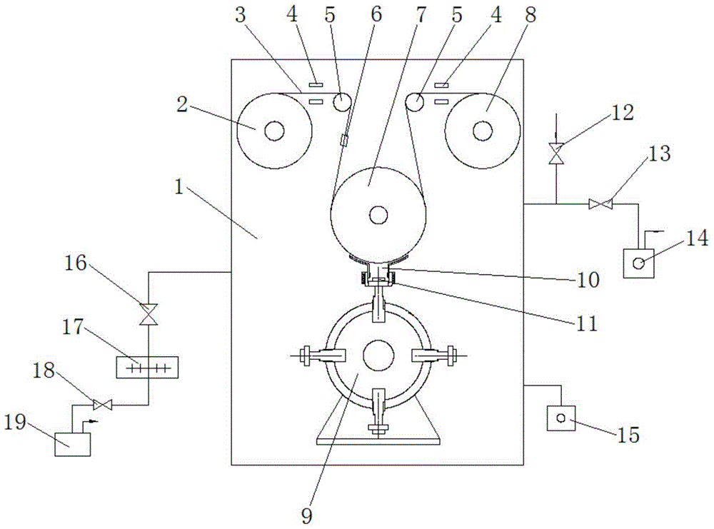
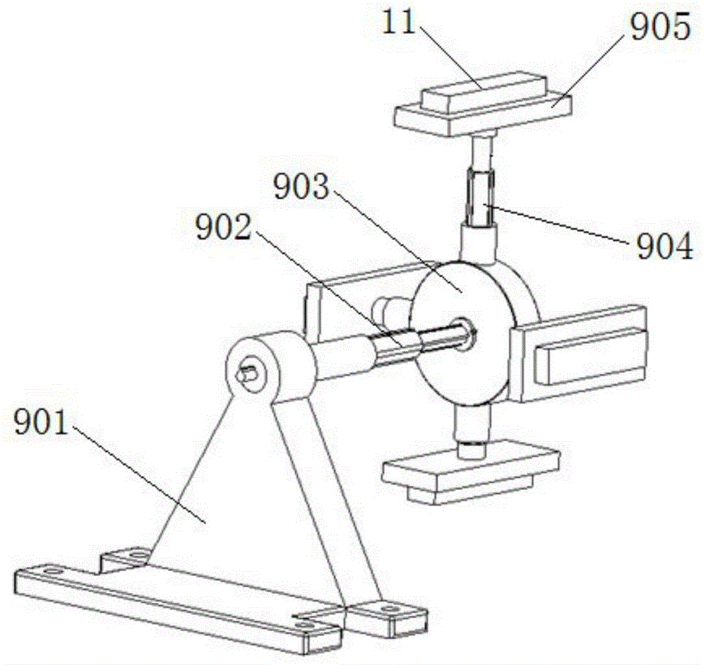
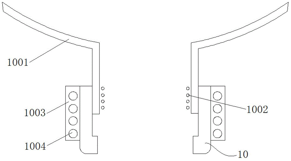
[0033] like figure 1 As shown, a single-sided reciprocating continuous coating magnetron sputtering roll-to-roll coating machine of the present embodiment includes a vacuum chamber 1, an uncoiling mechanism 2 sequentially arranged in the vacuum chamber 1, a cooling roller 7, a winding mechanism 8, an upper and lower The cathode cell 10 with openings on both sides, the return conversion target device 9 and the deviation correction device 4, the unwinding mechanism 2 and the winding mechanism 8 are respectively provided with a set of reversing rollers 5 for changing the direction of the base tape 3, the unwinding mechanism 2 and the winding mechanism 8 Located on both sides of the vacuum chamber 1, the cooling roller 7 is located at a downward position between the unwinding mechanism 2 and the winding mechanism 8, that is, the uncoiling mechanism 2, the winding mechanism 8 and the cooling roller 7 are basically located in an isosceles triangle On the three vertices, it is benefi...


PUM


Abstract

The invention discloses a magnetron sputtering winding coating machine capable of continuously coating in a single-sided reciprocated way, belonging to the field of vacuum coating equipment. The coating machine disclosed by the invention comprises a vacuum chamber, an unrolling mechanism, a cooling roller, a rolling mechanism, a small cathode chamber, a rotary target replacing device and two sets of error correcting devices, wherein the unrolling mechanism and the rolling mechanism are respectively provided with a set of error correcting device; the small cathode chamber and the rotary target replacing device are arranged at the lower part of the cooling roller, and the cooling roller, the small cathode chamber and the rotary target replacing device are located on the same axis; the rotary target replacing device comprises a stand, a rotary disk and electrode target seat plates uniformly distributed on the rotary disk; the electrode target seat plates rotate to the downside of the small cathode chamber and outwards extend so as to embed target cores into the small cathode chamber; and the unrolling mechanism and the rolling mechanism drive a base band to reciprocate. By using the magnetron sputtering winding coating machine, cathode targets can be replaced in time under the condition that the vacuum chamber for coating is not opened, a plurality of film layers are coated by virtue of reciprocation of a base material, and each layer of film is coated alone, so that film layer parameters are conveniently controlled; and the magnetron sputtering winding coating machine is compact in structure and small in occupied space.

Description

technical field [0001] The invention relates to a vacuum coating machine, more specifically, to a single-sided reciprocating continuous coating magnetron sputtering winding coating machine. Background technique [0002] Vacuum roll coating technology is a technology that prepares one or more layers of thin films with certain functions on the surface of the coil substrate by thermal evaporation or magnetron sputtering in a vacuum chamber. The vacuum winding coating equipment mainly has the following characteristics: first, the substrate to be coated is a flexible substrate, that is, it can be wound; second, the coating process is continuous, that is, the coating is carried out continuously within a working cycle; Third, the coating process is carried out in a high vacuum environment. During the unwinding and rewinding process of the winding coating machine, the surface of the substrate is coated with a thin film. The structure of the coating is the working part of the vacuum...

Claims


Application Information

Patent Timeline
Patent Type & Authority Patents(China)
IPC IPC(8): C23C14/56C23C14/35
CPCC23C14/35C23C14/562
Inventor 朱锡芳许清泉杨辉陈功徐安成
Owner LINGTONG EXHIBITION SYST
Why Eureka
Try Eureka