

Damping device for sliding door
A technology of damping device and sliding door, applied in the field of damping device, can solve the problems of not meeting the needs of users, inconvenient for processing and production, unable to use sliding doors, etc., to improve appearance cleanliness, eliminate contact noise, eliminate gaps and Effects of exposure to noise
- Summary
- Abstract
- Description
- Claims
- Application Information
AI Technical Summary
Problems solved by technology
Method used
Image

Examples
no. 1 example
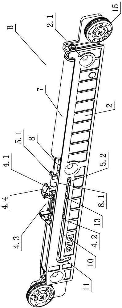
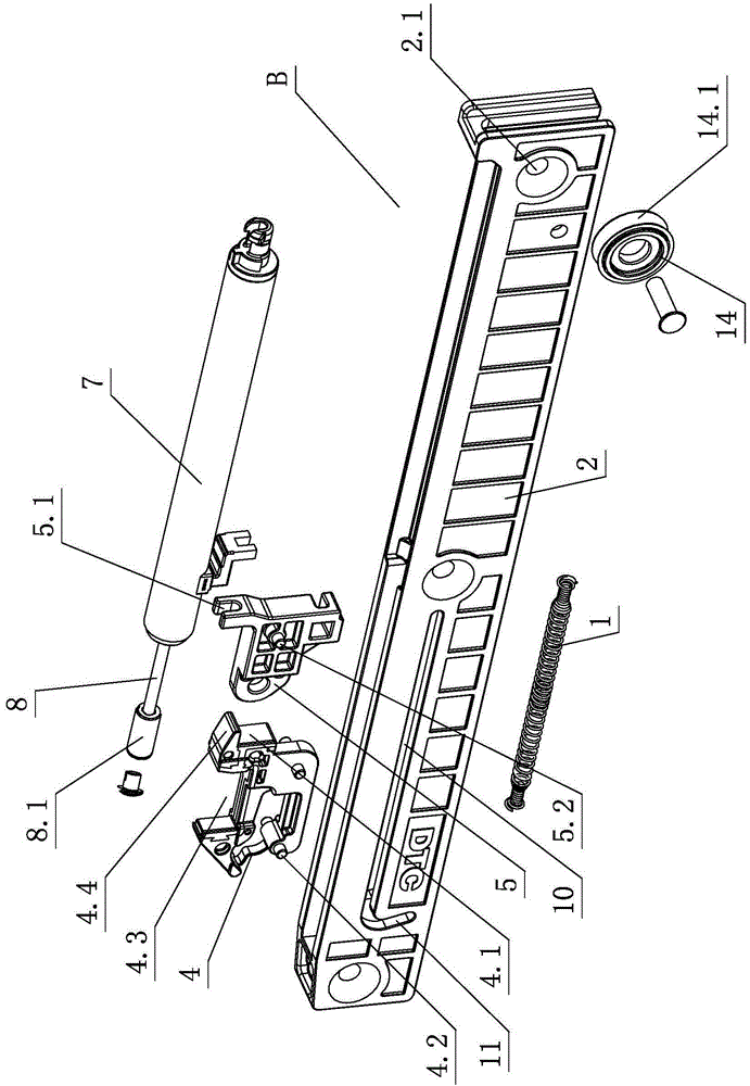
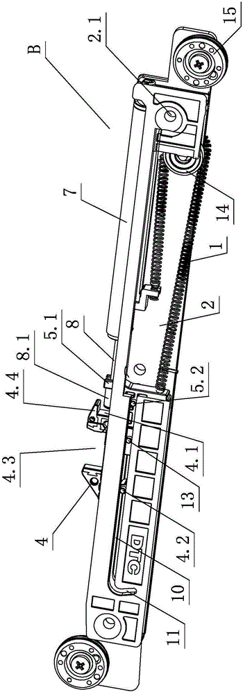
[0031] see Figure 1-Figure 12, the damping device for sliding doors, including fixed parts, movable parts, toggle mechanism A and damping mechanism B, toggle mechanism A includes a fixed part 3 and a toggle part 6, damping mechanism B includes a spring 1 sliding The swing piece 4 arranged on the fixed seat 2, the swing piece 4 is provided with a positioning notch 4.3 and collides with the toggle part 6, and the fixed seat 2 is provided with a damper 7, and the piston rod 8 of the damper 7 faces the swing piece 4 The direction protrudes, and at least a section of stroke acts on the swing member 4 when the damper 7 is buffered. The swing member 4 is connected; the toggle mechanism A is arranged on the fixed part, the damping mechanism B is arranged on the movable part, and is provided with a damping roller 15, and the damping roller 15 is positioned and rotated when the movable part moves. part and / or toggle mechanism A.
[0032] The steering member 14 is provided with a groo...
no. 2 example
[0042] see Figure 13-Figure 17 , this damping device for sliding doors is different from the first embodiment in that: the toggle mechanism A is set on the movable part and is provided with a toggle roller 18, and the damping mechanism B is set on the fixed part. The toggle roller 18 is positioned and rotated on the immovable component and / or the toggle mechanism A when the movable component moves.
[0043] Specifically, the toggle part 6 is fixedly arranged on the sliding door 20 through the fixing part 3, and the fixing part 2.1 is arranged on the fixing seat 2, and is fixedly arranged on the chute member 21 by setting a fastening unit on the fastening part 2.1. , the fixed part 3 is also provided with a toggle roller 18 through a pin shaft, and the toggle roller 18 is positioned and rotated on the chute member 21 and / or the toggle mechanism A when the sliding door 20 moves.
[0044] The toggle roller 18 is made of at least two different materials, wherein the material arr...
PUM
 Abstract
Description
Claims
Application Information