Solenoid actuator

A technology of solenoids and actuators, applied in the direction of engine components, machines/engines, valve devices, etc., can solve problems such as changes in the response of solenoid actuators

Inactive Publication Date: 2015-06-03
DENSO CORP
View PDF6 Cites 11 Cited by
  • Summary
  • Abstract
  • Description
  • Claims
  • Application Information

AI Technical Summary

Problems solved by technology

Thus, there will be variations in the responsiveness (also ...

Method used


Image

  • Solenoid actuator
  • Solenoid actuator
  • Solenoid actuator

Examples


Embodiment Construction

[0030] Embodiments according to the present invention and modifications thereof will be described with reference to the drawings.

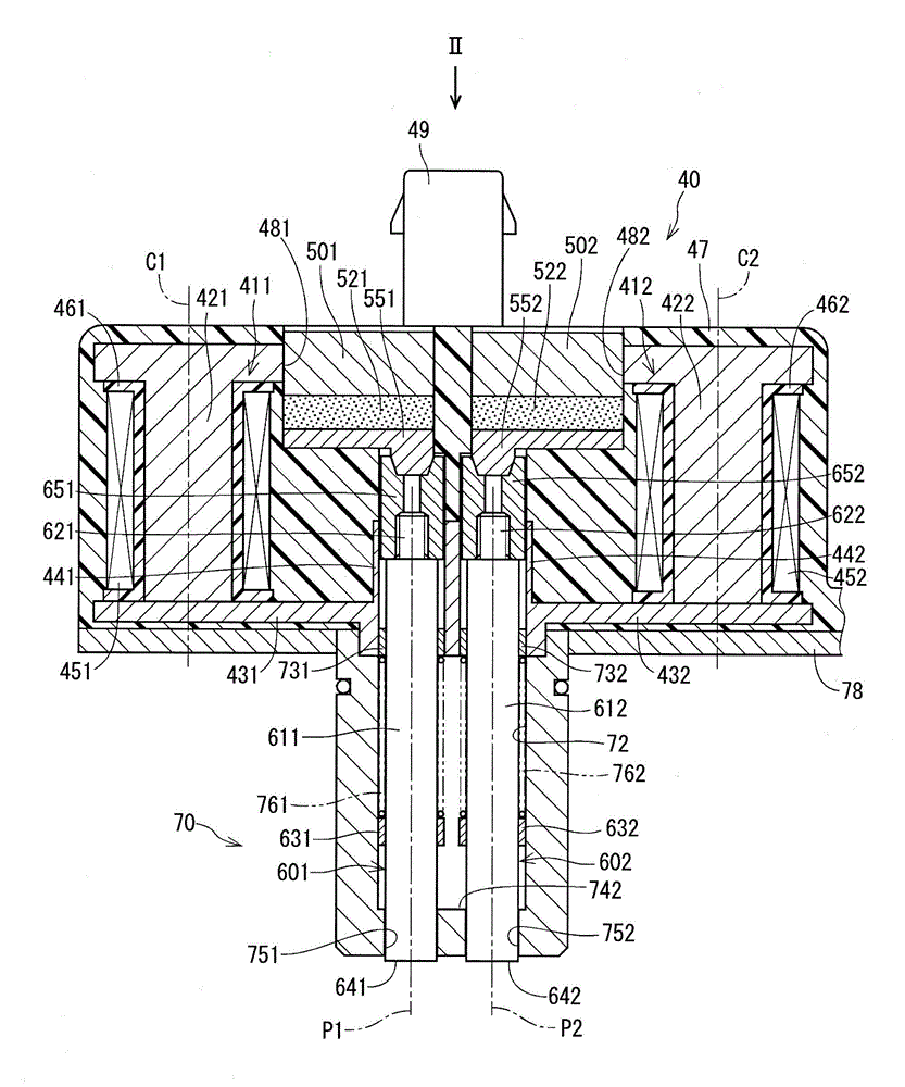
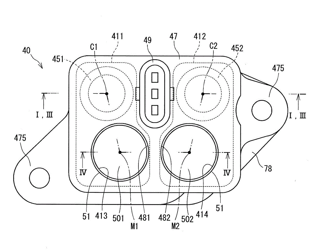
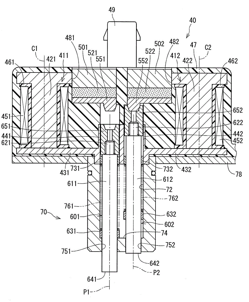
[0031] Similar to the solenoid actuator of JP2013-239538A (corresponding to CN103423503A), this embodiment and its modified solenoid actuator are suitable for adjusting the lift of the intake valve or exhaust valve of the internal combustion engine through a cam. In the valve lift adjusting device, the cam is integrally formed with a slider that can rotate integrally with the camshaft.

[0032] The slider of the valve lift adjusting device rotates integrally with the camshaft and is movable in the axial direction relative to the camshaft, and engagement grooves for gradually changing the axial position in response to the rotation angle are formed in the outer peripheral surface of the slider . Based on an instruction received from the control device (control device), the solenoid actuator moves one of the two restricting pins in the forward direc...


PUM


Abstract

The invention relates to a solenoid actuator. Adapters (551, 552) are provided to end parts of permanent magnets (521, 522) positioned at the side where plungers (651, 652) are placed. The adapter (551) collects flux of the permanent magnets (521, 522) and the collected flux is conducted to the plungers (651, 652). The adapters (551, 552) each includes a main body part (560) configured to be plate-shaped and a base (570), the base protrudes from the main body part (560) towards the plungers (651, 652) in a stepped manner and is opposite to the plungers (651, 652) at a distance, and the distance can realize effective magnetic transmission between the base part (570) and the plungers (651, 652). The base (570) is symmetrical about a vertical line (y) vertical to a reference line (x). The reference line (x) is a straight line connected between a central axis (M) of the main body part (560) and a central axis (Q) of the base (570).

Description

technical field [0001] The invention relates to a solenoid actuator for a valve lift adjustment device of an internal combustion engine. Background technique [0002] In a known type of valve lift adjusting device for adjusting the lift amount of an intake valve or an exhaust valve of an internal combustion engine, the position of a slide member which can rotate integrally with the camshaft and which can move axially relative to the camshaft is adjustable. change. Also, one such solenoid actuator selectively operates one of the two restricting pins based on the moving direction of the slider so as to engage the distal end portion of the restricting pin to an engagement groove formed in the slider. [0003] For example, in the solenoid actuator described in JP2013-239538A (corresponding to CN103423503A), two permanent magnets are fixed to the stationary part in such a way that the direction of the S pole to the N pole of one of the permanent magnets is the same as that of th...

Claims


Application Information

Patent Timeline
IPC IPC(8): F01L13/00
CPCF01L13/0036F01L2013/0052F01L2013/101F01L2820/031H01F7/16
Inventor 天野均
Owner DENSO CORP
Why Eureka
Try Eureka