
Self-holding solenoid valve

A solenoid valve, self-maintaining technology, applied in the direction of lift valve, valve details, valve device, etc., can solve the problems of loose closing, complex structure and high processing accuracy requirements

Active Publication Date: 2015-06-03
NINGBO JLT ELECTRIC CO LTD
View PDF6 Cites 7 Cited by
  • Summary
  • Abstract
  • Description
  • Claims
  • Application Information

AI Technical Summary

Problems solved by technology

[0003] The existing solenoid valve needs a valve seat in the valve body, which has the disadvantages of complex structure, high processing precision and easy closure

Method used


Image

  • Self-holding solenoid valve
  • Self-holding solenoid valve

Examples


Embodiment Construction

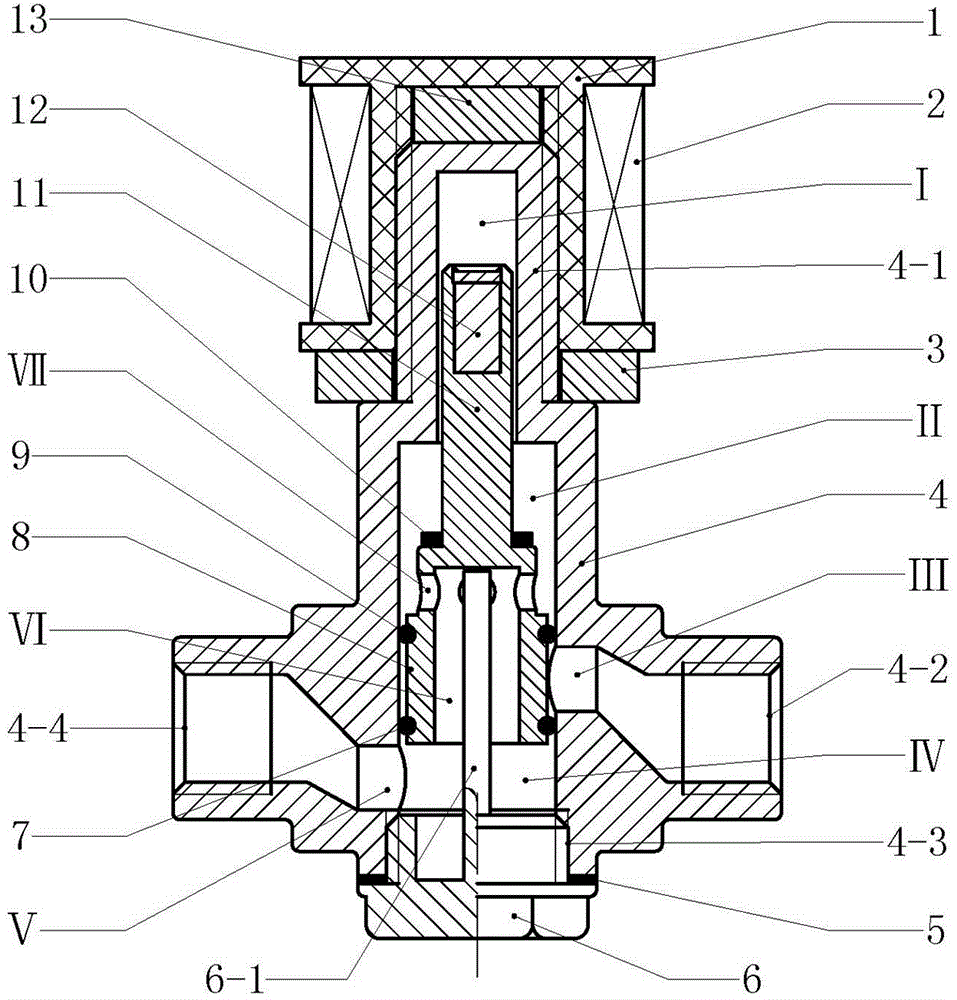
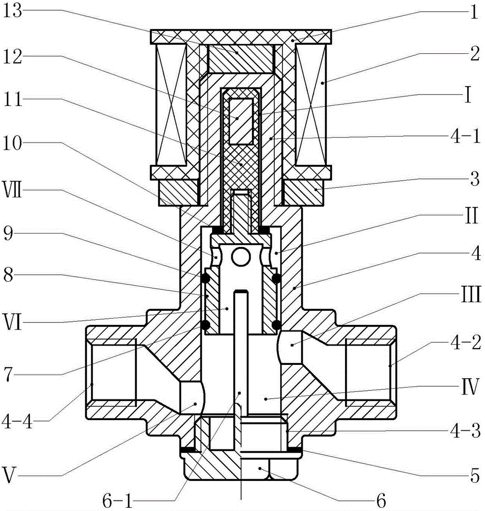
[0016] Example Attached figure 1 or attached figure 2In the embodiment shown, the self-holding solenoid valve is mainly composed of a valve body, a valve core, a sliding connecting rod, a bottom cover (6) and an electromagnetic coil, wherein the valve body (4) is an integrated structure, and the valve body (4) ) contains connecting rod slideway (Ⅰ), piston slideway and valve chamber (IV), connecting rod slideway (I) is above the piston slideway, valve chamber (IV) is below the piston slideway, and connecting rod slideway The channel (I), the piston slideway and the valve chamber (IV) are connected with each other. There is a fluid outlet (Ⅲ) connected to the wall of the piston slideway, and a fluid inlet (Ⅲ) on the wall of the valve chamber (IV). Ⅴ) access, the valve body has an input interface (4-4) and an output interface (4-2), the input interface (4-4) is connected to the fluid inlet (Ⅴ) on the wall of the valve cavity (IV), and the output The interface (4-2) is connect...


PUM


Abstract

The invention provides a self-holding solenoid valve and relates to a solenoid valve. The self-holding solenoid valve comprises a valve body, a valve element, a sliding connecting rod and an electromagnetic coil, wherein a connecting rod slide way, a piston slide way and a valve cavity are arranged in the valve body; a fluid outlet output is arranged on a wall body of the piston slide way and a fluid inlet input is arranged on a wall body of the valve cavity; the valve element is in a hollow piston structure; a through hole is formed in the side wall of the upper part of the piston structure; an upper sealing ring and a lower sealing ring are arranged on the outer side of the middle wall body of the piston structure and on the outer side of the lower part wall body of the piston structure; an iron magnet is arranged in the upper end body of the sliding connecting rod; the sliding connecting rod is connected with the upper end of the valve element; the valve element is arranged in the piston slide way; the sliding connecting rod stretches into the connecting rod slide way; an isobaric cavity is formed by a piston slide way space above the upper sealing ring; the valve cavity is communicated with the isobaric cavity by a fluid channel and a through hole in the valve element; the electromagnetic coil is mounted at the periphery of the wall body of the connecting rod slide way. According to the self-holding solenoid valve, valve switching-on / off operation can be smoothly carried out without overcoming the pressure of fluid; a valve seat is not arranged in the valve body so that the structure of the solenoid valve is simple.

Description

technical field [0001] The invention relates to an automatically controlled electromagnetic appliance, in particular to an electromagnetic valve. Background technique [0002] Solenoid valves include gas solenoid valves, steam solenoid valves, water solenoid valves, oil solenoid valves and refrigeration solenoid valves. Solenoid valves are widely used in household appliances, textiles, light industry, and urban construction industries as actuators for automatic control of fluid media. . The solenoid valve uses electromagnetic force to act on the iron core sealed in the magnetic sleeve to complete the valve opening action. There is no dynamic seal, so it can avoid leakage. Therefore, the solenoid valve has the characteristics of safe use, especially suitable for corrosive, toxic Or high and low temperature media. [0003] The existing solenoid valve needs a valve seat in the valve body, which has the disadvantages of complex structure, high processing precision and easy clo...

Claims


Application Information

Patent Timeline
Patent Type & Authority Applications(China)
IPC IPC(8): F16K31/06F16K1/00F16K1/36F16K1/46F16K27/02
CPCF16K1/36F16K1/46F16K27/029F16K31/0655
Inventor 郑哲鹏
Owner NINGBO JLT ELECTRIC CO LTD
Learn More