Thin oil lubricating device

A technology of thin oil lubrication and lubricating pump, applied in the direction of engine lubrication, presses, engine components, etc., can solve problems such as oil leakage

Inactive Publication Date: 2015-06-03
上海天和制药机械有限公司
View PDF5 Cites 4 Cited by
  • Summary
  • Abstract
  • Description
  • Claims
  • Application Information

AI Technical Summary

Problems solved by technology

[0003] The purpose of the present invention is to provide a thin oil lubricating device to solve the problem of quantitative oil lubricatio

Method used


Image

  • Thin oil lubricating device

Examples


Embodiment Construction

[0006] The thin oil lubricating device of the present invention will be further described below with reference to the accompanying drawings and examples.

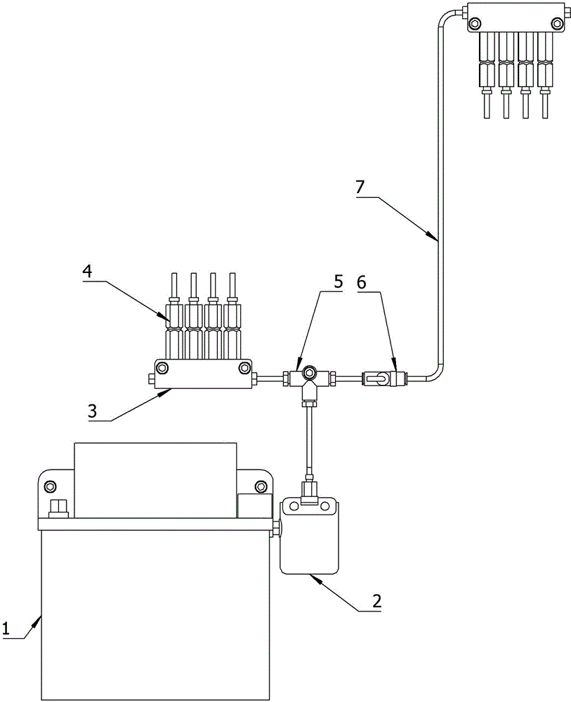
[0007] Such as figure 1 As shown, the thin oil lubricating device of the present invention includes an electric lubricating pump 1, an oil filter 2, a multi-way oil separation block 3, a quantitative oil injector 4, a three-way joint 5, a one-way throttle valve 6 and an oil pipe 7, wherein the filter After the oiler 2 is installed on the electric lubricating pump 1, it is connected with the three-way joint 5 through the oil pipe 7, and the three-way joint is divided into two roads to connect with the multi-way oil distribution block 3 respectively, and one-way throttle valve 6 is installed in one oil road , Quantitative lubricator 4 is respectively installed on the multi-pass oil distribution block 3 and then connected to each lubricating point through the oil pipe, and the lubricating period, lubricating time and lubricati...


PUM


Abstract

The invention discloses a thin oil lubricating device used on a tablet press in pharmaceutical machinery to achieve quantitative lubricating oil adding for an upper track, a lower track, an upper drift nail and a lower drift nail. The thin oil lubricating device comprises a motor-driven lubricating pump, an oil filter, a multi-way oil distribution block, quantitative oil injectors, a three-way connector, a one-way throttling valve and an oil pipe. The oil filter is installed on the motor-driven lubricating pump and connected with the three-way connector through the oil pipe, the three-way connector is connected with the multi-way oil distribution block in two ways, wherein the one-way throttling valve is installed in one oil way, the quantitative oil injectors are installed on the multi-way oil distribution block and connected to lubricating oil points through oil pipes, and lubricating period, lubricating time and lubricating oil quantity are set by means of control of the motor-driven lubricating pump by the electric control system. The thin oil lubricating device can serve as an upgraded product of a mechanical oil cup oil filling device arranged on the existing rotating tablet press.

Description

technical field [0001] The invention relates to a lubricating device on a pharmaceutical machine, in particular to a thin oil lubricating device on a rotary tablet press in the pharmaceutical machine. Background technique [0002] In my country's pharmaceutical machinery industry, there are many ways to use mechanical oil cups for the lubrication system on rotary tablet presses. At present, the common low-speed tablet presses in the market only use mechanical oil cups to lubricate the upper punch nails, and the lower punches and lower rails are not lubricated. When the oil in the oil cup is large, there is a little lubrication effect, and when the oil in the oil cup When the quantity is low or there is no oil, the direct dry friction between the punch and the upper rail will easily cause damage to the machine parts and shorten the service life of the machine; on medium and high-speed tablet presses, the upper punch and the upper rail are also lubricated by mechanical oil cup...

Claims


Application Information

Patent Timeline
IPC IPC(8): F16N7/38
CPCB30B11/08B30B15/0088
Inventor 严学生赵志能
Owner 上海天和制药机械有限公司
Why Eureka
Try Eureka