Simulative testing device and method of drilling tool thread dynamic fatigue

A technology of dynamic fatigue and simulation testing, applied in measuring devices, vibration testing, testing of machine/structural components, etc., to achieve smooth transmission, real-time monitoring data recording, and easy use.

Inactive Publication Date: 2015-06-03
SOUTHWEST PETROLEUM UNIV
View PDF5 Cites 15 Cited by
  • Summary
  • Abstract
  • Description
  • Claims
  • Application Information

AI Technical Summary

Problems solved by technology

[0003] In order to solve the shortcomings of the existing fatigue test device, the present invention aims to provide a dynamic fatigu

Method used


Image

  • Simulative testing device and method of drilling tool thread dynamic fatigue
  • Simulative testing device and method of drilling tool thread dynamic fatigue
  • Simulative testing device and method of drilling tool thread dynamic fatigue

Examples


Embodiment Construction

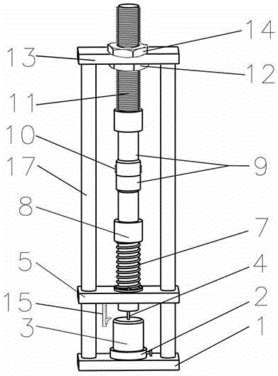
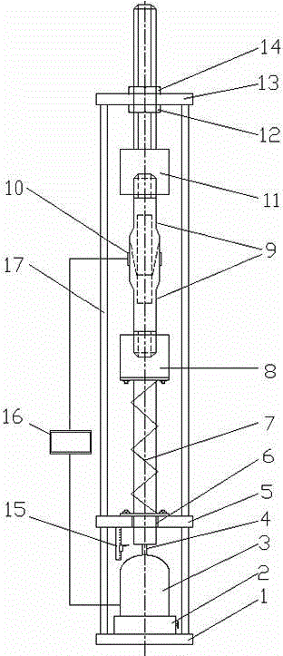
[0029] The present invention will be described in detail below in conjunction with the accompanying drawings.

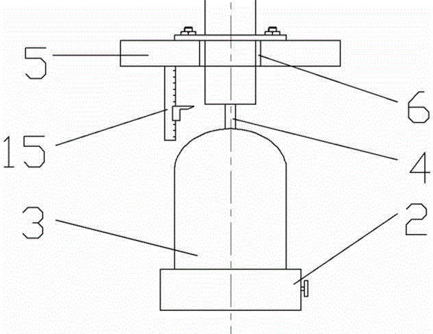
[0030] Such as figure 1 , figure 2 As shown, the present invention comprises a base 1, a fine-tuning lifting device 2 located at the center of the base 1, a vibrator 3 located on the fine-tuning lifting device 2, a base plate 5 located above the vibrator 3, and a base plate located above the base 5. Top plate 13, the sliding bearing 6 that is located at the center of the bottom plate 5, the lower connecting column 8 are installed in the sliding bearing 6, the vernier caliper 15 that is located at the lower end surface of the bottom plate 5, the upper connecting column 11 that is located at the center of the top plate 13, and the upper connecting column 11 that is located at the bottom plate 5 and The spring 7 between the lower connecting columns 8, the tension nut 14 arranged on the upper part of the upper connecting column 11, the compression nut 12 arranged on th...


PUM


Abstract

The invention relates to a simulative testing device and method of drilling tool thread dynamic fatigues in the technical field of petroleum and natural gas drilling engineering. The device comprises a base, a fine adjustment lifting device, a vibration exciter, a sliding bearing, a lower connection column, a vernier calliper, an upper connection column, a spring, a tensile nut, a compressive nut, a strain gauge and a measurement and control host. In the method, two parts including a static load module and a dynamic load module are adopted, wherein a static load is simulated by utilizing a spring mechanism; and a dynamic load is simulated by using a vibration excitation mechanism. By adopting the technical scheme, static tensile and compressive loads can be applied to a testing tubular column; dynamic excitation in different forms can also be applied; real-time monitoring and data recording of strain, exciting force and excitation frequency can be realized; and the device is simple in structure and convenient to use.

Description

technical field [0001] The invention relates to the technical field of drilling engineering in the petroleum and natural gas industry, in particular to a dynamic fatigue simulation test device and method for drilling thread. Background technique [0002] In the process of oil drilling, the service environment of the drill pipe is harsh and the force is complicated, and it is often faced with a serious risk of drilling tool failure. Thread failure is an important form of oil drill pipe failure, and the fracture of thread connection is the most serious and destructive accident of drilling tool connection failure. The main reason for thread fracture is that there is a stress fatigue zone at the thread connection. When the stress fatigue reaches a certain limit during use, the thread will suddenly break. Therefore, to prevent fatigue damage and reduce the occurrence of fracture accidents at the thread of downhole drilling tools, it is necessary to do a good job in performance e...

Claims


Application Information

Patent Timeline
IPC IPC(8): G01M7/02
Inventor 曾德智何奇垚侯铎施太和林元华喻智明陆凯张智任建
Owner SOUTHWEST PETROLEUM UNIV
Why Eureka
Try Eureka