
Blade tip jet test device

A test device, blade top injection technology, applied in aerodynamic test, jet engine test, measuring device, etc.

Inactive Publication Date: 2015-06-03
CHINA SHIP DEV & DESIGN CENT
View PDF6 Cites 25 Cited by
  • Summary
  • Abstract
  • Description
  • Claims
  • Application Information

AI Technical Summary

Problems solved by technology

[0008] However, at present, domestic research on blade tip injection control for gap flow is still at the numerical simulation stage, and there is no corresponding test device to study the blade tip injection scheme.

Method used


Image

  • Blade tip jet test device
  • Blade tip jet test device
  • Blade tip jet test device

Examples


Embodiment Construction

[0029] The present invention will be further described below in conjunction with the accompanying drawings. The preferred embodiments of the present invention are only used to help explain the present invention and are not intended to limit the protection scope of the present invention. The preferred embodiments of the invention do not exhaustively describe all details, nor do they limit the invention to the described specific implementations. Obviously, many modifications and variations can be made based on the contents of this specification. This description selects and specifically describes these embodiments in order to better explain the principle and practical application of the present invention, so that those skilled in the art can make good use of the present invention. The invention is to be limited only by the claims, along with their full scope and equivalents. After reading the contents of the present invention, those skilled in the art can make various changes ...


PUM


Abstract

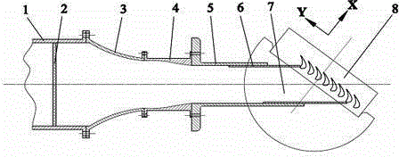
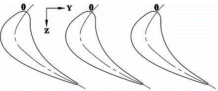
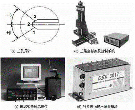
A blade tip jet test device comprises a subsonic turbine cascade wind tunnel. The wind tunnel comprises a fan, a pressure stabilizing barrel, a honeycomb, convergence devices, an inlet section, a movable side plate, a test cascade, and a rotatable semi disk. The cascade is composed of blades. The device further comprises a sheet used for making blade tips, and blade tip jet holes which are distributed in the range of chord length at a distance from the front edge of the blades and are adjustable. In the thickness direction of the blades, the tangential jet angle, flow-direction jet angle and jet flow of the jet holes can be adjusted. Static pressure holes are distributed on the surfaces of the test blades. Test points are distributed on the section of the exit of the cascade. An optimal jet scheme is obtained in the invention, the performance of the scheme in the range of attack angle of an actual blade is verified, and whether the blade tip jet scheme has industrial practical popularization value can be well verified.

Description

[0001] technical field [0002] The invention relates to the performance field of a marine gas turbine, in particular to a test device for reducing the internal gap flow loss of the gas turbine through an active control method so as to improve the efficiency and overall output power of the gas turbine. [0003] Background technique [0004] Gas turbine is the core power equipment of high-power ships in the 21st century, and its development level can reflect the advanced level of a country's shipbuilding industry, so it needs to be vigorously developed. The flow loss inside the runner is one of the main factors restricting the efficiency of gas turbines, so many research institutions regard it as the focus of their research. [0005] The gap flow loss is one of the important components of the internal flow loss of the rotor blade. In high-pressure turbines, 45% of the flow loss in the moving blades and 30% of the flow loss in the turbine stage are caused by gap flow. Studi...

Claims


Application Information

Patent Timeline
Patent Type & Authority Applications(China)
IPC IPC(8): G01M15/14G01M9/02G01M9/06
Inventor 牛茂升李为赵辉钟琮伟王建德
Owner CHINA SHIP DEV & DESIGN CENT
Learn More