
Automatic optical identification system suitable for radio frequency identification label quality checking

A technology for identifying labels and quality inspection, applied in the direction of collaborative devices, instruments, computer parts, etc., can solve problems such as unfavorable adjustment, inability to give offset dimensions, low accuracy of human eyes, etc., to improve yield and output , reducing the effect of human eye accuracy and inefficiency

Active Publication Date: 2015-06-03
SHANGYANG RFID TECH YANGZHOU
View PDF10 Cites 1 Cited by
  • Summary
  • Abstract
  • Description
  • Claims
  • Application Information

AI Technical Summary

Problems solved by technology

Existing methods rely on human eyes and the experience of inspectors. The disadvantages are: 1) Due to the low accuracy of human eyes, they can only make fuzzy judgments. 2) The frequency of the human eye cannot keep up with the speed of the machine, which limits the production capacity of the machine. The speed of the compound machine exceeds 20m / min, and the human eye can no longer see clearly The appearance of the antenna pattern is clear, and the maximum speed of the composite machine is 90m / min; 3) There is no record of various sizes, and it is impossible to analyze the composite process

Method used


Image

  • Automatic optical identification system suitable for radio frequency identification label quality checking
  • Automatic optical identification system suitable for radio frequency identification label quality checking
  • Automatic optical identification system suitable for radio frequency identification label quality checking

Examples


Embodiment Construction

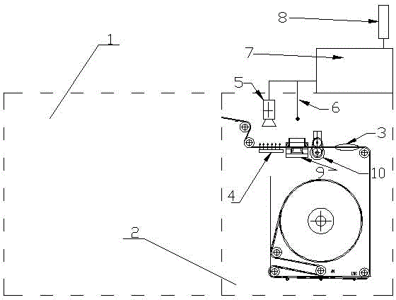
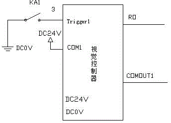
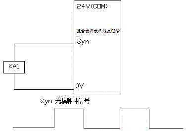
[0016] Further illustrate the present invention in conjunction with accompanying drawing and embodiment, as figure 1 As shown, the present invention comprises the compound machine that has compound equipment production part 1 and comprises the compound equipment winding part 2 of reader-writer 9, pressing roller 10, and product roll 3 at the front end of reader-writer 9 of compound equipment winding part 2 A plane light source 4 is fixed on the machine platform on one side, and a camera 5 is fixed on the machine platform on the other side corresponding to the product volume 3 of the plane light source 4, and the output of the camera 5 is connected to the AOI controller. When the composite machine is produced, each label will use a reader to detect the radio frequency signal, so each label will give a trigger signal. The present invention is to connect the trigger signal 6 in parallel, and the visual controller in the control box 7 receives the trigger signal. After the sig...


PUM


Abstract

The invention relates to an automatic optical identification system suitable for radio frequency identification label quality checking, and belongs to the technical field of optical automatic identification. The automatic optical identification system is characterized in that a planar light source is fixed on a cabinet on one side of a product roll at the front end of a reader-writer of a winding part of composite equipment; a camera is fixed on the cabinet on the other side of the product roll of the planar light source; the output of the camera is connected with an AOI controller in a control box; the reader-writer detects a triggering signal sent by each label, and the triggering signal is connected with the vision controller Trigger1 end in the AOI controller. According to the automatic optical identification system, the reader-writer is used for detecting that each label sends the triggering signal, and each RFID label is shot at ultra-high shooting speed; after high-speed image processing calculation of the AOI controller is carried out, whether the various sizes are greater than an upper set limit and a lower set limit is judged. The automatic optical identification system can be used for detecting each RFID label and providing a deflection value of the relevant size of each label; the detection speed can be matched with the highest speed of the cabinet, so that abnormal products caused by human eye precision and efficiency are reduced, and the qualification rate and the yield of products are improved.

Description

technical field [0001] The invention relates to an automatic optical identification system suitable for quality inspection of radio frequency identification tags, belonging to the technical field of optical automatic identification. Background technique [0002] The radio frequency identification label (RFID) is glued on the laminating machine, and the upper and lower composite surface materials and substrates are die-cut to make labels that can be torn off and attached to other objects. Because it is roll-to-roll production , Tension will affect the stability of the tape, and there will be a knife that will die-cut the material other than the substrate into labels one by one, so the resulting instability will make the knife cut to the antenna pattern, resulting in defective products. The existing method is to recognize the distance from the die-cut edge to the antenna pattern by human eyes in the winding part of the composite equipment, and adjust the machine if there is an...

Claims


Application Information

Patent Timeline
IPC IPC(8): G06K17/00
Inventor 伯林
Owner SHANGYANG RFID TECH YANGZHOU
Learn More