Pylon for mounting an engine on the structure of an aircraft

一种飞行器、发动机的技术,应用在动力装置的布置/安装、飞机上动力装置、燃气轮机式动力装置等方向,能够解决声级不利等问题,达到保证安全位置的效果

Active Publication Date: 2015-06-03
SN DETUDE & DE CONSTR DE MOTEURS DAVIATION S N E C M A
View PDF5 Cites 6 Cited by
  • Summary
  • Abstract
  • Description
  • Claims
  • Application Information

AI Technical Summary

Problems solved by technology

However, said configuration suspended under the wing is disadvantageous in terms of sound level due to the fact that when the aircraft follows an ascending path by tilting relative to its horizontally moving parts on take-off, the propeller encounter direction forms a non-zero angle with its axis of rotation airflow

Method used


Image

  • Pylon for mounting an engine on the structure of an aircraft
  • Pylon for mounting an engine on the structure of an aircraft

Examples


Embodiment Construction

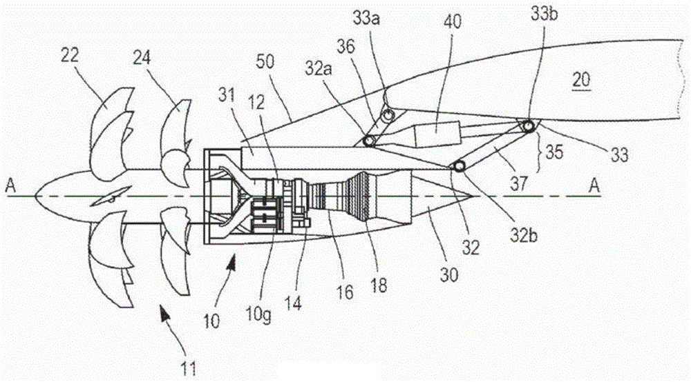
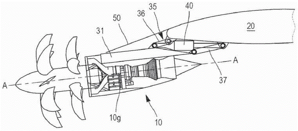
[0021] refer to figure 1 , an "open rotor" turboshaft engine 10 can be seen, this expression designating a pair of ductless propellers. The pair of propellers 11 is arranged upstream of the engine along an extension of the axis of rotation of the engine. The engine comprises, from upstream to downstream in the direction of the air flow in the engine, an air intake communicating with a compressor 12 , an annular combustion chamber 14 and two turbines 16 and 18 . The turbines are each connected to one of the rotors 22, 24 of the propeller it drives.

[0022] Airflow entering compressor 12 is compressed and then mixed with fuel and combusted in combustor 14 . The combustion gases are then injected into the turbine to rotate the rotor of the propeller, which supplies the major part of the thrust produced by the engine. Combustion gases exit the turbine and are expelled through duct 30 in order to increase thrust.

[0023] The propellers 22, 24 are coaxial and arranged in tande...


PUM


Abstract

The invention relates to a system for pylon attachment system (31) for mounting an engine (10) on the structure of an aircraft, in particular to the wings, comprising a first attachment means (31) which can be secured to the pylon and a second attachment means (32) which can be secured to the structure of the aircraft. The pylon is characterised in that it comprises a connection means (35) connecting the first and second attachment means, said connection means being arranged to allow the movement of the first attachment means in relation to the second attachment means between first and second positions. Figure pour l'abrégé : figure 1.

Description

technical field [0001] The invention relates to the mounting of a propulsion engine on a structure of an aircraft. The invention relates in particular to the installation of an engine including an upstream propeller. Background technique [0002] Propulsion engines on an aircraft may be mounted at various points on the fuselage or wings. When a propulsion engine on an aircraft is mounted suspended below the wing, struts or booms connect the propulsion engine to the structure of the wing through the lower surface of the structure of the wing. For reasons of space constraints and aerodynamic constraints, the engine extends upstream at least partially beyond the leading edge of the wing on which it hangs. [0003] The invention relates in particular to an engine comprising a propeller in an upstream position. The propeller may be, for example, a single propeller in a turboprop or a twin propeller formed by two counter-rotating rotors. The present invention relates more part...

Claims


Application Information

Patent Timeline
Patent Type & Authority Applications(China)
IPC IPC(8): B64D27/26
CPCB64D27/12B64D2027/005Y02T50/60B64D27/402B64D27/40B64C11/48
Inventor 弗朗索瓦·加莱帕特里克·卓伊兹
Owner SN DETUDE & DE CONSTR DE MOTEURS DAVIATION S N E C M A
Why Eureka
Try Eureka