Head-up display for a vehicle

A field of view display and vehicle technology, applied in optical components, optics, instruments, etc., can solve the problems of enlarged optical path, multi-structure space, etc., and achieve the effect of reducing structural space, large field of view, and reducing demand

Inactive Publication Date: 2015-06-03
ROBERT BOSCH GMBH
View PDF8 Cites 4 Cited by
  • Summary
  • Abstract
  • Description
  • Claims
  • Application Information

AI Technical Summary

Problems solved by technology

Larger beam path and higher number of optical elements lead to more installation space required for field of view displays

Method used


Image

  • Head-up display for a vehicle
  • Head-up display for a vehicle
  • Head-up display for a vehicle

Examples


Embodiment Construction

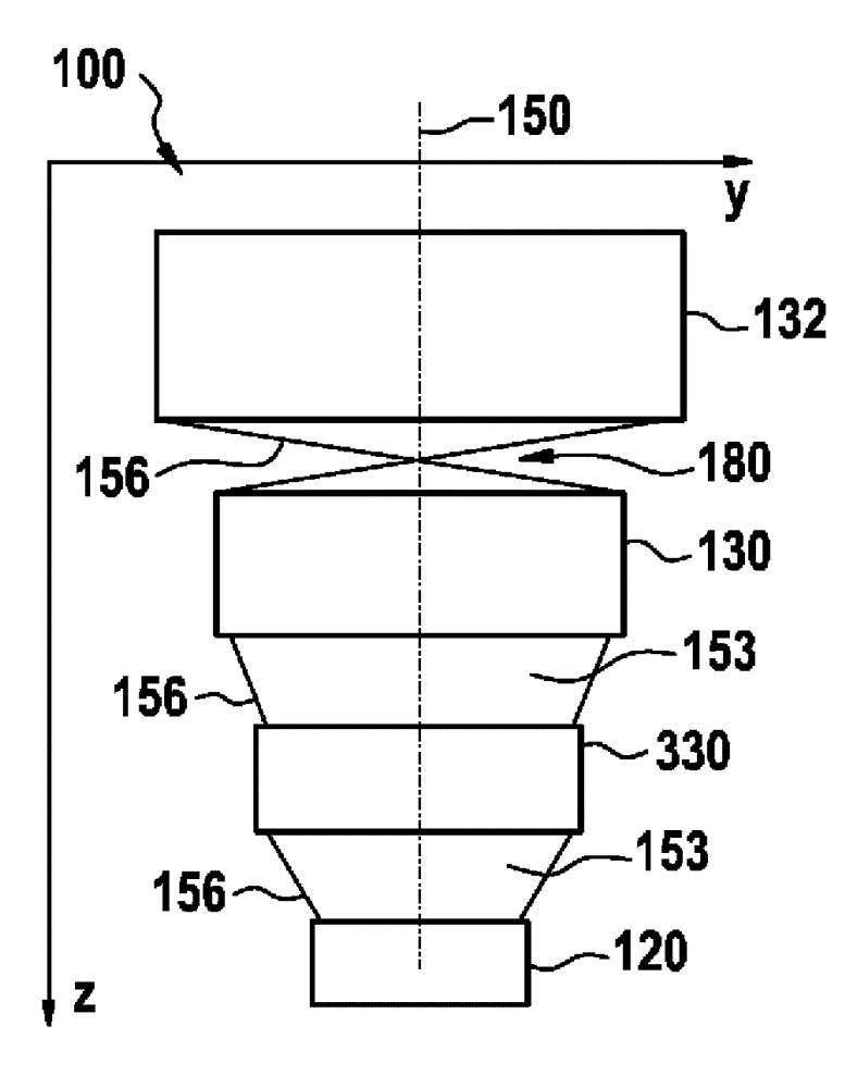
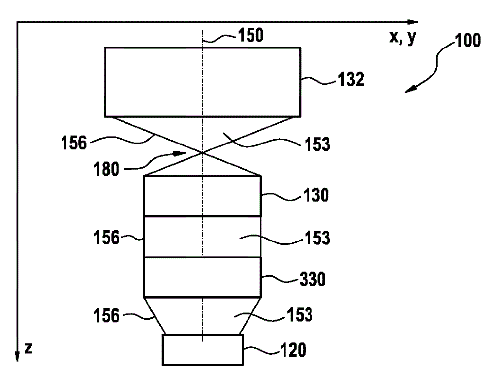
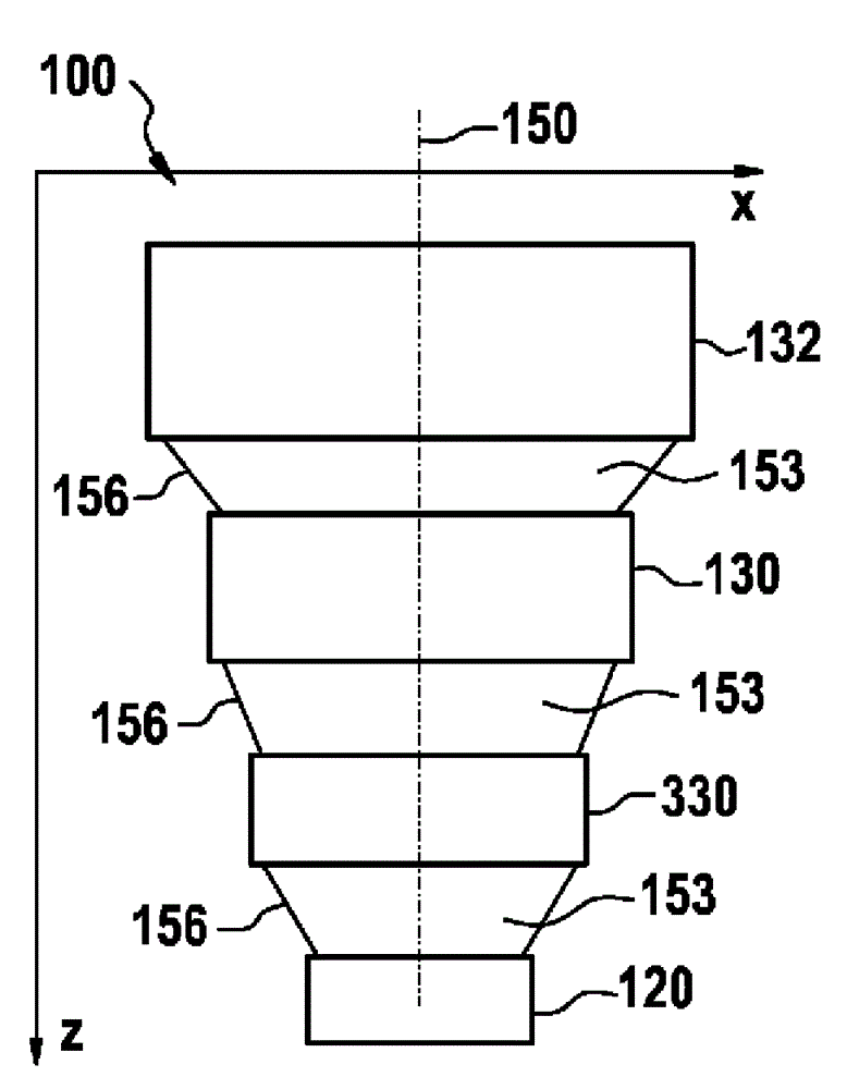
[0033] figure 1 A schematic diagram of field of view display device 100 in vehicle 110 according to an exemplary embodiment of the present invention is shown. Field of view display device 100 is arranged in vehicle 110 as a head-up display. The illustrated field of view display device 100 includes an image signal generator (Bildgeber) 120 , a first optical element 130 , a second optical element 132 , and a third optical element 134 , and uses a windshield 140 of a vehicle 110 as a projection surface. The windshield 140 is reflective, light transmissive glass.

[0034] The field of view display device 100 has an optical axis 150 . The image signal generator 120 is designed to provide image information, which is projected in a beam body 153 delimited by an edge 156 of the beam body 153 in the line of sight direction 160 of a vehicle occupant 170 . Between the first optical element 130 and the second optical element 132 , the field of view display device has a central focus 18...


PUM


Abstract

The invention relates to a head-up display (100) for a vehicle (110) for displaying image information in a line of vision (160) of a vehicle occupant (170). The invention is characterized in that optical elements (130, 132, 134) are designed to form a beam volume (153) carrying image information and having an intermediate focus (180) acting in a direction in space.

Description

technical field [0001] The invention relates to a field of view display device for a vehicle. Background technique [0002] A field of view display device is a display device with which information can be faded into the field of vision of a vehicle occupant. For example, information from driver assistance systems can be faded into the driver's field of vision. The field-of-view display device is also known as a head-up display or the acronym HUD (Head up Display). The field of view display device illuminates the transparent surface or window surface with the information image, so that the imaged light of the information is reflected into the eyes of the observer, who sees through the transparent surface. Compared to conventional displays on the dashboard, the field of view display offers the advantage that the viewer does not have to divert his field of view from the actual traffic situation in order to detect the information conveyed by means of the field of view display....

Claims


Application Information

Patent Timeline
Patent Type & Authority Applications(China)
IPC IPC(8): G02B27/01
CPCG02B27/0101G02B2027/0123G02B2027/0145G02B2027/015
Inventor S.施泰因科格勒J.魏因加滕
Owner ROBERT BOSCH GMBH
Why Eureka
Try Eureka