3D-printing cervical vertebra side block screw guide embedded plate and manufacturing method thereof

A 3D printing and guide plate technology, which is applied in medical science, surgery, fixers, etc., can solve the problems of not being able to guide the lateral mass screw into the screw, and not being able to guide multiple cervical vertebral lateral masses, so as to ensure accuracy and reduce the difficulty of fitting , Simple and easy operation

Active Publication Date: 2015-06-10
BEIJING FRIENDSHIP HOSPITAL CAPITAL MEDICAL UNIV
View PDF6 Cites 11 Cited by
  • Summary
  • Abstract
  • Description
  • Claims
  • Application Information

AI Technical Summary

Problems solved by technology

[0006] In order to overcome the problem that the existing technology can not guide the lateral mass screws well and can not guide multiple cervical lateral masses, the purpose of the present invention is to provide a 3D printed neck (cervical) that can solve the above problems 3-Cervical 7) Lateral mass screw-guided implant plate

Method used


Image

  • 3D-printing cervical vertebra side block screw guide embedded plate and manufacturing method thereof
  • 3D-printing cervical vertebra side block screw guide embedded plate and manufacturing method thereof
  • 3D-printing cervical vertebra side block screw guide embedded plate and manufacturing method thereof

Examples


Embodiment 1

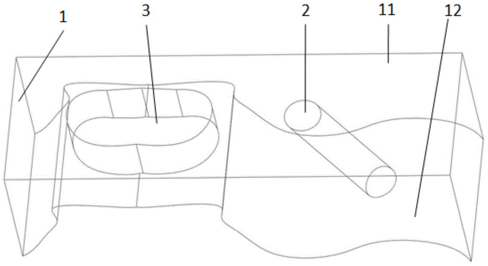
[0043] Example 1 3D printed cervical lateral mass screw-guided implant plate structure

[0044]A 3D printed cervical lateral mass screw-guided implant plate, including a solid guide plate 1, the size of which can cover a cervical lateral mass; There is also a spinous process hole 3; the spinous process hole 3 is located on the side of the guide plate 1, and the guide nail track 2 is set beside the spinous process hole 3. Track 2, the screw can accurately enter the lateral mass. The upper part of the guide plate 1 is a flat surface 11, and the curved surface 12 at the bottom of the guide plate 1 is consistent with the opposite direction of the surgical lamina; one side of the bottom curved surface 12 of the guide plate 1 extends to the outside of the side mass, and one side extends to the other side of the spinous process, and the curved surface of the bottom of the guide plate is vertically thickened to The upper plane of the guide plate. The shape of the spinous process hol...

Embodiment 2

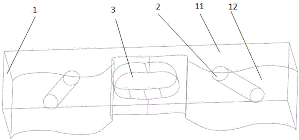
[0046] Example 2 3D printed cervical lateral mass screw-guided implant plate structure

[0047] A 3D-printed cervical lateral mass screw-guided implant plate, including a solid guide plate 1, the size of which can cover a cervical lateral mass; There is also a spinous process hole 3; the spinous process hole 3 is located in the center of the guide plate 1, and two guide nail tracks 2 are arranged on both sides of the spinous process hole 3, and the direction of the guide screw track 2 is consistent with the direction of the lateral mass screw screw entry track. Guide screw channel 2, the screw can accurately enter the lateral mass. The upper part of the guide plate 1 is a plane 11, and the bottom curved surface 12 of the guide plate 1 can be consistent with the operation lamina; the bottom curved surface 12 of the guide plate 1 extends to the outside of the side blocks on both sides, and the bottom curved surface of the guide plate is vertically thickened to the upper plane of...

Embodiment 3

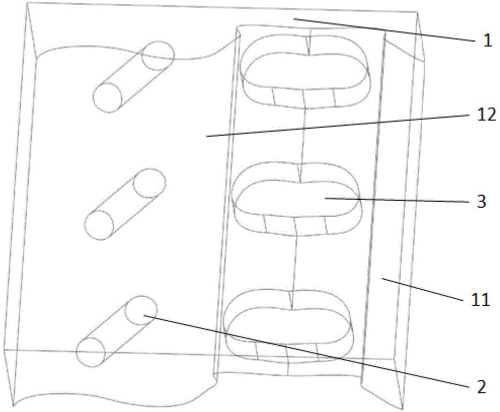
[0049] Example 3 3D printed cervical lateral mass screw-guided implant plate structure

[0050] A 3D-printed cervical lateral mass screw-guided implant plate, including a solid guide plate 1, the size of which can cover three cervical vertebral lateral masses; There are also three spinous process holes 3; the spinous process holes 3 are located on one side of the guide plate 1, and the guide nail track 2 is set on the other side of the guide plate 1. Screw channel 2, the screw can accurately enter the lateral mass. The upper part of the guide plate 1 is a flat surface 11, and the curved surface 12 at the bottom of the guide plate 1 is consistent with the opposite direction of the surgical lamina; one side of the bottom curved surface 12 of the guide plate 1 extends to the outside of the side mass, and one side extends to the other side of the spinous process, and the curved surface of the bottom of the guide plate is vertically thickened to The upper plane of the guide plate....


PUM


Abstract

The invention discloses a 3D-printing cervical vertebra side block screw guide embedded plate and a manufacturing method thereof. The embedded plate is printed through 3D printing technology and comprises one or multiple guide plates, one to multiple side block screw guide screw paths and one to multiple spinous holes formed in the center or one side of the guide plate, the upper portion of the guide plate is a plane, the curved surface of the bottom of the guide plate is reversely uniform with a cervical vertebra side block vertebral plate, the curved surface of the bottom of the guide plate is uniform to the outer side of a side block, and the plane of the upper portion of the guide plate extends to an outlet, in the upper-portion plane, of the corresponding screw path and then extends for 2-5mm. When multiple guide plates are arranged, connecting components are arranged among the guide plates. In order to guarantee stability of the guide embedded plate, fixing needles different in amount are arranged on the guide plates, and fixing clamps are arranged beside the spinous holes. The 3D-printing cervical vertebra side block screw guide embedded plate is simple and reasonable in structure and convenient to use, a screw feeding guide screw path can be provided for cervical vertebra side block screws effectively, accuracy (depth and direction) of screw feeding is guaranteed, and operating difficulty and operating risk are reduced.

Description

technical field [0001] The invention belongs to a guiding medical device for posterior cervical surgery, in particular to a 3D-printed cervical lateral mass screw-guiding implant plate. Background technique [0002] At present, clinically, for the posterior surgical treatment of patients with neck diseases, the surgical methods that are often considered include posterior cervical "single-door" or "double-door" laminoplasty or different methods of decompression surgery. During the operation, in order to maintain the stability of the cervical motion segment and maintain the physiological lordosis of the cervical spine, the internal fixation of the cervical lateral mass screw rod internal fixation system is usually added at the same time of decompression, and the lateral mass screw used to connect the metal rod is mostly in the When traveling on the lateral mass in the posterior cervical spine, there are strict requirements on the screw insertion direction and angle of the late...

Claims


Application Information

Patent Timeline
Patent Type & Authority Applications(China)
IPC IPC(8): A61B17/90B33Y10/00B33Y50/00B33Y80/00
CPCA61B17/88A61B17/90
Inventor 费琦杨雍王炳强李东李锦军孟海马钊苏楠林吉生王奇张效栋
Owner BEIJING FRIENDSHIP HOSPITAL CAPITAL MEDICAL UNIV
Why Eureka
Try Eureka