Method for welding stainless steel optical units without cutting steel belt and corresponding tool structure

A technology of stainless steel and optical unit, which is applied in the field of optical communication, can solve the problems of increased production cost due to the cost of the cutter, low steel strip utilization rate, and high production cost, so as to avoid secondary welding, improve utilization rate, and meet the requirements of laser welding Effect

Active Publication Date: 2015-06-10
FUJIKURA HENGTONG AERIAL CABLE SYST +2
View PDF12 Cites 3 Cited by
  • Summary
  • Abstract
  • Description
  • Claims
  • Application Information

AI Technical Summary

Problems solved by technology

[0004] It can be seen from the table that as the size of the forming die increases, the utilization rate of the steel strip increases. However, due to the limitation of the elongation of the steel strip and the diameter of the light unit, the use of large-size forming dies is bound to be limited. The utilization rate is low, so that the production cost is high; and in the existing method, the cost of the cutting knife also further increases the production cost due to the need for the steel strip to be cut.
To sum up, the original method of trimming the opposite sides of the steel strips and then performing longitudinal cladding welding has high production costs.

Method used


Image

  • Method for welding stainless steel optical units without cutting steel belt and corresponding tool structure
  • Method for welding stainless steel optical units without cutting steel belt and corresponding tool structure
  • Method for welding stainless steel optical units without cutting steel belt and corresponding tool structure

Examples


Embodiment Construction

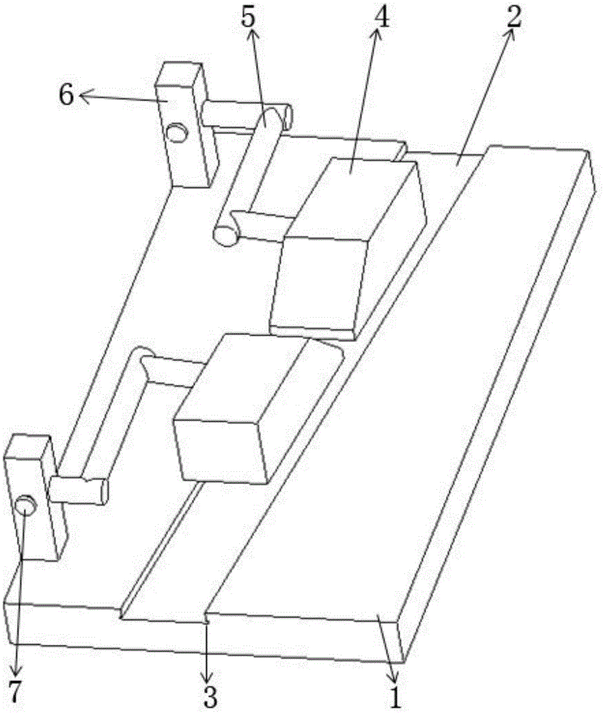
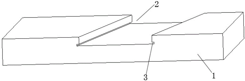
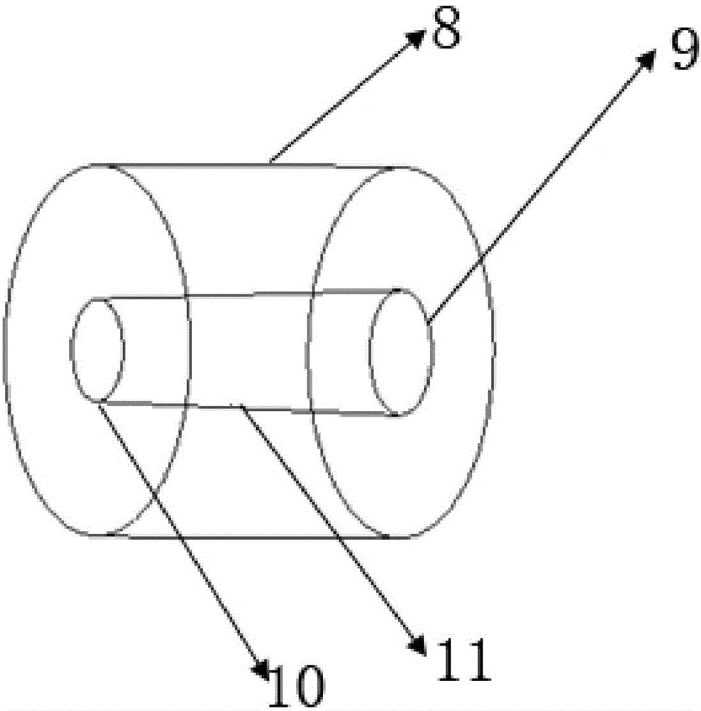
[0029] A method for welding stainless steel light units without cutting strips. After covering the edge positions on both sides of two sections of steel strips that need to be connected on opposite sides, and then welding the exposed opposite side connection positions through welding equipment, the two sections of steel strips are completed. The opposite side is connected, and then the steel strip formed as a whole is placed on the steel strip rack. After the steel strips are released by the two steel strip racks at the same time, the stainless steel tube is formed through the longitudinal wrapping mold, and the stainless steel tube is formed in the longitudinal wrapping mold. During the forming process, the laser continuous welding device welds the edge positions on both sides of the covered steel strip.

[0030] After covering the edge positions on both sides of the two steel strips that need to be connected on opposite sides, the operation of welding the exposed opposite sid...


PUM

PropertyMeasurementUnit
thicknessaaaaaaaaaa
widthaaaaaaaaaa
thicknessaaaaaaaaaa

Abstract

The invention provides a method for welding stainless steel optical units without cutting steel belt, and has the advantages of overcoming the defects at the butting parts, satisfying the requirements of laser welding and directly welding without cutting steel belts so as to reduce the production cost. The method comprises the following steps: shielding the border positions on two sides of two steel belts needing opposite side connection; welding the exposed opposite side connection positions through welding equipment to complete the opposite side connection of the two steel belts; placing the integrated steel belt on two steel belt placing frames; forming stainless steel pipes through a longitudinal tubing die after the two steel belt placing frames discharge the steel belts at the same time; welding the shielded border positions on the two sides of the steel belts by a laser continuous welding device in the process of forming the stainless steel pipes in the longitudinal tubing die.

Description

technical field [0001] The present invention relates to the technical field of optical communication, and specifically relates to a method for welding stainless steel optical units without cutting strips. The invention also provides a tooling structure corresponding to the method for welding stainless steel optical units without cutting strips. Background technique [0002] Most domestic companies currently use laser welding technology for optical fiber composite overhead ground wires (OPGW for short) and optical fiber composite overhead phase wires (OPPC for short). The steel strip with a certain width is cut into the steel strip with the corresponding width of the forming die owned by the company, and some waste edges are subtracted, so that some steel strips are wasted in the production of sleeves. Usually, the company uses more than one set of forming molds, such as φ5.0, φ4.6, φ3.5 and other specifications of forming molds. Different forming molds require different widt...

Claims


Application Information

Patent Timeline
Patent Type & Authority Applications(China)
IPC IPC(8): B23K26/70B23K26/21B23K26/60
CPCB23K26/20
Inventor 伍光磊徐大鹏
Owner FUJIKURA HENGTONG AERIAL CABLE SYST
Why Eureka
Try Eureka