Fuel tank system
A fuel tank and fuel technology, applied in the direction of the substructure, etc., can solve the problems of complex fuel tank formation, reduced fuel tank capacity, etc., and achieve the effects of easy maintenance, simplified installation, and simple shape
- Summary
- Abstract
- Description
- Claims
- Application Information
AI Technical Summary
Problems solved by technology
Method used
Image

Examples
Embodiment Construction
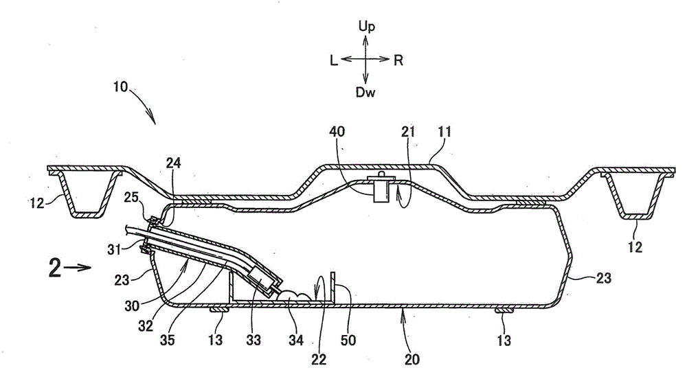
[0041] Hereinafter, the form for implementing this invention is demonstrated based on drawing. It should be noted that "front", "rear", "left", "right", "up", and "down" refer to the direction viewed from the driver, and Fr indicates the front side, Rr indicates the rear side, and L indicates the left side. Side, R means the right side, Up means the upper side, and Dw means the lower side.
[0042] 【Example】
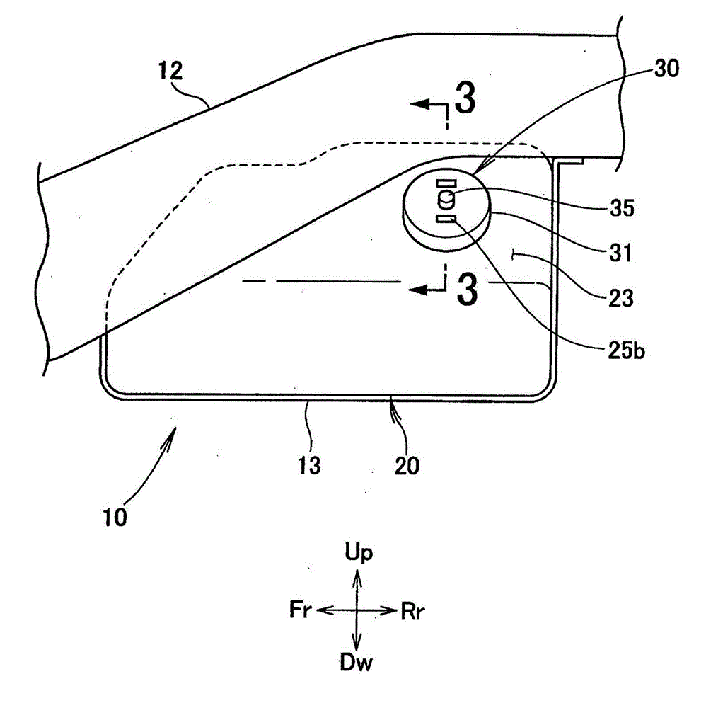
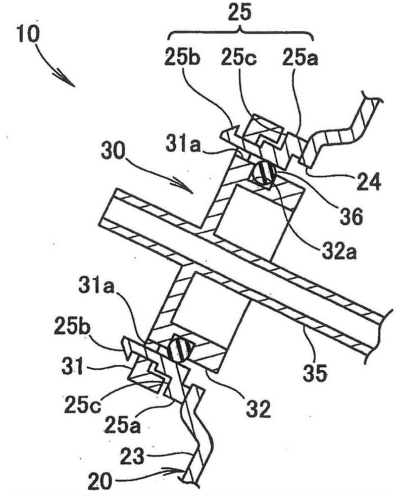
[0043] The fuel tank system according to the embodiment will be described. Such as figure 1As shown, the fuel tank system 10 has: a fuel tank 20, which is disposed under the bottom plate 11 and stores fuel; a fuel pump assembly 30, which is disposed in the fuel tank 20; a ventilation valve 40, which is disposed on the top of the fuel tank 20 21 ; the reservoir 50 integrally provided at the bottom 22 of the fuel tank 20 .
[0044] The fuel pump assembly 30 is used to send the fuel in the fuel tank 20 to the outside. The vent valve 40 is a fuel shutoff valve that allo...
PUM
 Abstract
Description
Claims
Application Information