
A multi-phase link-wheel drive mechanism

A wheel-driven, multi-phase technology, used in motor vehicles, transportation and packaging, etc., can solve the problems of link-type mechanism movement interference, inability to take into account stability, balance obstacle-crossing ability, etc., and achieve efficient and reliable obstacle-crossing process. High barrier effect, simple control effect

Active Publication Date: 2017-03-08
SOUTHWEST UNIV
View PDF7 Cites 0 Cited by
  • Summary
  • Abstract
  • Description
  • Claims
  • Application Information

AI Technical Summary

Problems solved by technology

[0006] In view of this, the purpose of the present invention is to provide a multi-phase link-wheel drive mechanism, which can overcome the obstacles that the existing obstacle-crossing mechanism cannot take into account the stability and balance of the walking mechanism on regular terrain and the obstacle-crossing under irregular terrain. ability, and can effectively solve the "singularity" problem; on flat ground, it can move efficiently in a wheeled manner, and in irregular terrain, it can effectively pass through obstacles with the help of multi-phase linkage linkage, which solves the movement of linkage mechanisms interference problem

Method used


Image

  • A multi-phase link-wheel drive mechanism
  • A multi-phase link-wheel drive mechanism
  • A multi-phase link-wheel drive mechanism

Examples


Embodiment Construction

[0023] The preferred embodiments of the present invention will be described in detail below with reference to the accompanying drawings.

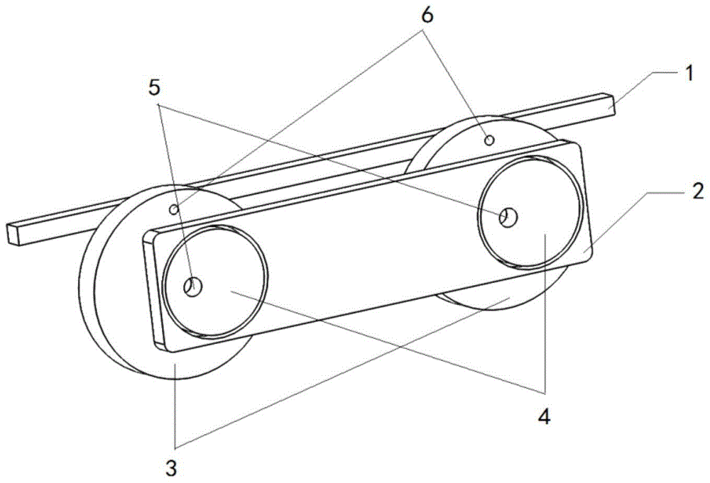
[0024] figure 1 It is a three-dimensional structure diagram of the present invention, and for the convenience of description, only the parts related to the present invention are given.

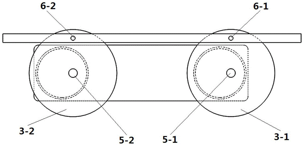
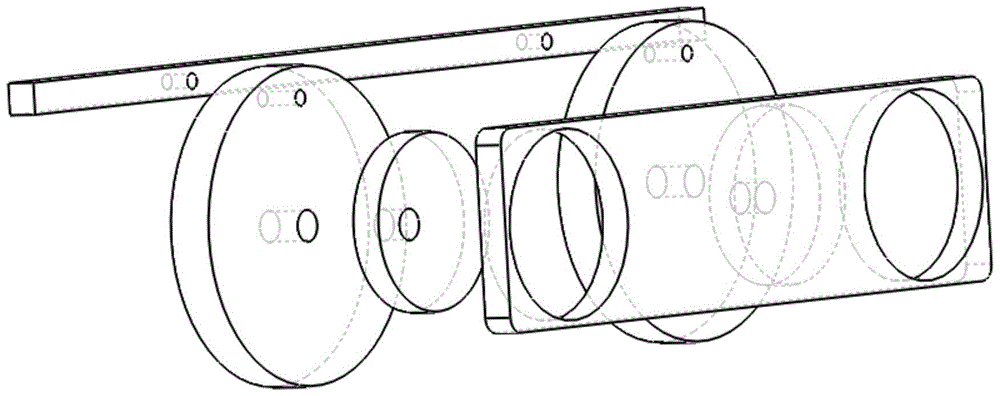
[0025] A multi-phase linkage wheel drive mechanism, in this embodiment, taking n=2 (two action wheels on each side) as an example, includes action wheels (3-1) and action wheels (3-2) and is connected to The over-obstacle connecting rod (1) on the action wheel (3) is respectively provided with a positioning hole (6-1) and a positioning hole (6-2) on the over-obstacle connecting rod (1), and the movable pin shaft passes through the positioning hole ( 6) The action wheel (3) is connected with the obstacle-crossing connecting rod (1), and the positioning hole (6) on the action wheel (3) is close to the position of the circumference of the wheel. The axle cen...


PUM


Abstract

The invention relates to a multiphase connecting rod wheel driving mechanism comprising travelling wheels, an obstacle-crossing connecting rod, small wheels and a sheet connecting rod connected to the small wheels. Positioning holes are formed in the travelling wheels and the obstacle-crossing connecting rod. Movable pins pass through the positioning holes to connect the travelling wheels with the obstacle-crossing connecting rod. One small wheel is mounted on each travelling wheel and is completely fixed relative to the corresponding travelling wheel. Each small wheel is not concentric with the corresponding travelling wheel and covers the circle center of the corresponding travelling wheel. Power shafts are positioned on the circle centers of the travelling wheels. An included angle is formed by a connecting line between the circle center of each small wheel and the axis of the corresponding travelling wheel and a connecting line between the corresponding connecting rod positioning hole and the axis of the travelling wheel, in other words, the two connecting lines do not coincide. A plurality of round grooves are formed in the sheet connecting rod. The sheet connecting rod is embedded on the small wheels through the round grooves externally. The diameter of each round groove is slightly larger than that of each small wheel. The small wheels are embedded in the round grooves internally and can rotate freely in the round grooves. The sheet connecting rod rotates around the power shafts along with the small wheels. The mechanism is simple to control and has a concise travelling mechanism, can solve the problem of 'singular points' effectively and has remarkable advantages as compared with other travelling mechanisms.

Description

technical field [0001] The invention relates to a driving device, in particular to a multi-phase link wheel driving mechanism. Background technique [0002] Obstacle-surmounting mechanism is an important part in the field of mobile robots and has a wide range of applications in real life. With the frequent occurrence of natural disasters, forest fires, nuclear accidents, earthquake rescue and other events and the growth of human exploration of unknown areas, human beings are eager to perceive these environments in order to collect information, alleviate disasters, and rescue the wounded. Therefore need a kind of obstacle-crossing mechanism to help people to solve this problem. At present, the used obstacle surmounting mechanisms mainly include wheel type, crawler type, leg type, hybrid type, connecting rod type and other structures. Low ground pressure, good adhesion and passing performance on soft ground, high stability in climbing stairs and obstacle surmounting, but the...

Claims


Application Information

Patent Timeline
Patent Type & Authority Patents(China)
IPC IPC(8): B62D57/024
CPCB62D57/02
Inventor 王宇俊方灿廖书斌黄结蒋齐密
Owner SOUTHWEST UNIV
Learn More