Conveying trolley group, accompanying connecting device and air friction conveying system

A technology for conveying trolleys and connecting devices, applied in conveyors, mechanical conveyors, transportation and packaging, etc., can solve problems such as decoupling, trolley disconnection, conveyor line disconnection, etc., to improve reliability and stability, and to cooperate closely and firmly , to avoid the effect of decoupling

Active Publication Date: 2015-06-10
HUBEI HUACHANGDA INTELLIGENT EQUIP
View PDF8 Cites 7 Cited by
  • Summary
  • Abstract
  • Description
  • Claims
  • Application Information

AI Technical Summary

Problems solved by technology

[0005] In order to ensure the accompanying stability of the conveying trolley group, in the prior art, a connection device A that interlocks up and down is provided between the conveying trolleys, such as figure 1 As shown, but the connecting device A will produce decoupling phenomenon under the action of a large impact force between the conveying carts, causing the accompanying carts to be out of joint, resulting in the disconnection of the conveying line

Method used


Image

  • Conveying trolley group, accompanying connecting device and air friction conveying system
  • Conveying trolley group, accompanying connecting device and air friction conveying system
  • Conveying trolley group, accompanying connecting device and air friction conveying system

Examples


Embodiment Construction

[0044] In the following description, numerous specific details are set forth in order to provide a thorough understanding of the present invention. However, the present invention can be implemented in many other ways different from those described here, and those skilled in the art can make similar extensions without violating the connotation of the present invention, so the present invention is not limited by the specific implementations disclosed below.

[0045] The implementation of the present invention will be described in detail below in conjunction with the accompanying drawings, and the present invention will be described by taking the conveying trolley group applied to the aerial friction conveying system as an example.

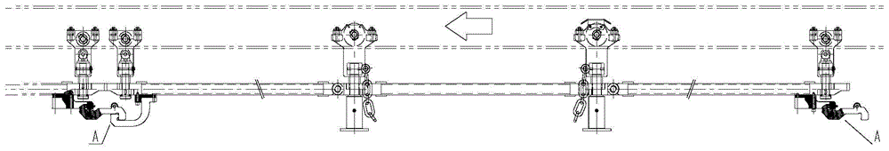
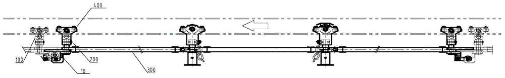
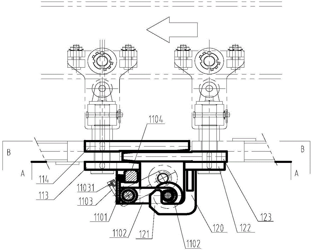
[0046] Please refer to figure 2 as shown, figure 2 It is a structural schematic diagram of a transport trolley set provided by the present invention. In this embodiment, the transport trolley set includes: at least two trolleys arranged in sequen...


PUM


Abstract

The invention discloses a conveying trolley group, an accompanying connecting device and an air friction conveying system. The conveying trolley group comprises at least two trolleys arranged in the running direction in sequence; the accompanying connecting device is arranged between the opposite ends of the adjacent two trolleys and comprises a pothook and a hanging buckle matched with the pothook; the pothook comprises a pothook handle and a pothook bending part fixedly arranged at one end of the pothook handle; the hanging buckle comprises a hanging arm and a hanging shaft; during connection, the hanging shaft falls into the pothook bending part of the pothook under the rotation of the hanging arm around the connecting shaft, so that the front trolley and the rear trolley which are adjacent are connected with each other; during disengagement, the hanging buckle rotates in the opposite direction during falling, so that the hanging shaft is separated from the pothook bending part, and the accompanying reliability and stability of the conveying trolley are improved.

Description

technical field [0001] The invention relates to a conveying mechanical device, in particular to a conveying trolley group, an accompanying connection device and an air friction conveying system. Background technique [0002] The friction conveyor line is widely used in the field of mechanized transportation due to its advantages of simple structure, stable operation, convenient maintenance, energy saving, low noise and no oil pollution. Example: Automobile production line. [0003] The main application scope of the friction conveying line in the automobile production line is: the transportation and storage line from the welding body-in-white to the painting workshop, the pre-painting treatment line, the PVC painting line, the wax spraying line for painting, and the painted body from painting to final assembly Conveyor storage line, final assembly chassis assembly line and door sub-assembly line, etc. [0004] The friction conveyor line includes a ground friction conveyor l...

Claims


Application Information

Patent Timeline
Patent Type & Authority Applications(China)
IPC IPC(8): B65G35/00
Inventor 程志强
Owner HUBEI HUACHANGDA INTELLIGENT EQUIP
Why Eureka
Try Eureka