Automatic turning device for thrust ball bearing ferrule

A thrust ball bearing, automatic technology, applied in the direction of transportation and packaging, conveyor objects, etc., can solve the problems of reduced production efficiency, energy waste, increased production costs, etc., to avoid scrap, avoid unequal grinding, and improve production. The effect of efficiency

Active Publication Date: 2015-06-10
浙江盛达物联科技股份有限公司
View PDF10 Cites 12 Cited by
  • Summary
  • Abstract
  • Description
  • Claims
  • Application Information

AI Technical Summary

Problems solved by technology

[0002] The thrust ball bearing ring is one of the bearing rings. The thrust ball bearing ring has the structural feature that only one of the end faces is provided with a groove. The thrust ball bearing ring grinding or ultra-finishing equipment requires the ring groove Clamping towards the tool, if an automatic feeding device is used for automatic feeding, the rings are required to be oriented during the automatic feeding process, and the current automatic feeding bins output the end faces of the bearing rings at random Yes, manual inspection and manual turning are often required during the feeding and conveying process, which increases labor intensity and reduces production efficiency; when encountering large quantities, manual inspection will inevitably lead to mistakes, so that the end faces of the bearing rings do not form a uniform orientation , it is prone to quality problems such as unequal grinding and car crash, which will make the workpiece scrapped, resulting in energy waste and increased production costs

Method used


Image

  • Automatic turning device for thrust ball bearing ferrule

Examples


Embodiment Construction

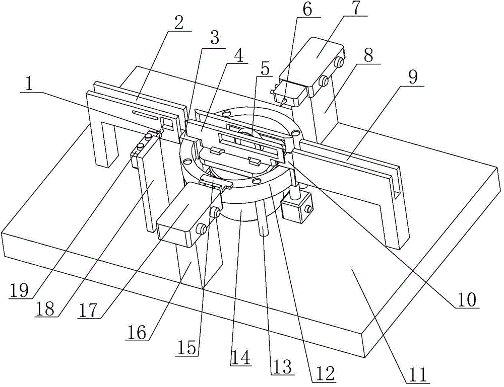
[0013] Specific embodiments of the present invention will be described in detail below in conjunction with the accompanying drawings.

[0014] Such as figure 1 As shown, the present invention comprises base 11, feed channel 2, quantification mechanism, automatic surface turning mechanism, positioning mechanism, detection mechanism, discharge channel 9 and control system, and described automatic surface turning mechanism comprises motor 14, and section becomes U-shaped The positioning feedway and the circular retaining ring 12 that wraps the positioning feedway in the center, the circular retaining ring 12 is supported and fixedly installed on the base 11 by the support rod 13, and the top surface of the circular retaining ring 12 is higher than that of the positioning feedway The bottom surface prevents the workpiece 5 positioned in the positioning feedway from falling out of the positioning feedway when the positioning feedway is rotating. The circular stop ring 12 offers two...


PUM


Abstract

The invention discloses an automatic turning device for a thrust ball bearing ferrule, and belongs to the technical field of bearing production equipment. The automatic turning mechanism comprises a motor, a positioning material channel and a circular check ring, wherein the top surface of the circular check ring is higher than the bottom surface of the positioning material channel; a workpiece inlet and a workpiece outlet of the circular check ring are respectively provided with an inlet stop block and an outlet stop block; the bottom surface of one end, connected with the workpiece inlet, of the positioning material channel is always higher than the end connected with the workpiece outlet; when the two stop blocks fall down, the top surfaces of the two stop blocks are not higher than the bottom surface of the positioning material channel; a positioning mechanism and a detection mechanism are respectively arranged on the two sides of the positioning material channel; through holes for realizing pressing of the positioning mechanism and detection of the detection mechanism are respectively formed in two side baffles of the positioning material channel; a quantification mechanism is arranged on the side of a material feeding channel; a control system controls a motor, a positioning pressing block driving mechanism, a probe driving mechanism and a quantification mechanism and drives cylinders of the inlet stop block and the outlet stop block to operate. The automatic turning device meets the demand that the end faces of the ferrule are needed to uniformly face to a direction during processing of the thrust ball bearing ferrule.

Description

technical field [0001] The invention belongs to the technical field of bearing production equipment, and in particular relates to an automatic turning-over device for thrust ball bearing rings. Background technique [0002] The thrust ball bearing ring is one of the bearing rings. The thrust ball bearing ring has the structural feature that only one of the end faces is provided with a groove. The thrust ball bearing ring grinding or ultra-finishing equipment requires the ring groove Clamping towards the tool, if an automatic feeding device is used for automatic feeding, the rings are required to be oriented during the automatic feeding process, and the current automatic feeding bins output the end faces of the bearing rings at random Yes, manual inspection and manual turning are often required during the feeding and conveying process, which increases labor intensity and reduces production efficiency; when encountering large quantities, manual inspection will inevitably lea...

Claims


Application Information

Patent Timeline
Patent Type & Authority Applications(China)
IPC IPC(8): B65G47/244
Inventor 王国勇俞伟锋
Owner 浙江盛达物联科技股份有限公司
Why Eureka
Try Eureka