Prefabricated combined structure steel pipe pile wind power generation platform

A technology of combined structure and steel pipe piles, applied in the directions of underwater structures, infrastructure engineering, sheet pile walls, etc., can solve the problems of low efficiency, large workload, inconvenient operation, etc. The effect of increasing the strength of the connection

Active Publication Date: 2015-06-10
JSTI GRP CO LTD +1
6 Cites 1 Cited by

AI-Extracted Technical Summary

Problems solved by technology

[0004] The pile foundation structure of the existing offshore wind power generation platform is basically steel piles. The corrosion phenomenon of steel in seawater has always been an important fact...

Method used

After the reinforced concrete prefabricated platform 4 is installed, the upper steel pipe connecting section 1 is connected on the platform 4 by the anchor bolt 7, after the connection is completed, three steel supports 2 are uniformly set at the steel pipe connecting section 1 outer circumference to ensure its stability sex. The connecting section 1 of the wind power generation tower and the steel pipe is correspondingly connected through a flange.
During specific installation operation, piling machine drives foundation steel pile 11 into seabed 6 bearing layers and fixes, and the prefabricated pile 10 integrally hoisted to foundation steel pile 11 top surface elevation position by factory processing, passes through prefabricated pile The bayonet structure 13 at the lower end of 10 fixes the prefabricated pile 10 on the upper end of the foundation steel pile 11, and performs underwater grouting at the joint to ensure the installation strength.
Steel pipe connecting section 1 is vertically arranged with the platform 4 of horizontal setting, is positioned at the upper surface middle position of platform 4, and wherein connecting plate 3 is a circular structure, and circular connecting plate 3 is welded on the steel pipe connecting section 1 The bottom of the outer circumference is fixed on the platform 4 by bolts 4 . Three steel supports 2 are evenly arranged on the outer circumference of the steel pipe connection section 1, one end of the steel support 2 is connected to the upper surface of the platform 4, and the other end is connected to the outer circumference of the steel pipe connection section 1, wherein the steel support 2 is set at an angle of 45° to the horizontal plane ...

Abstract

The invention discloses a prefabricated combined structure steel pipe pile wind power generation platform. The prefabricated combined structure steel pipe pile wind power generation platform comprises a steel pipe connection section, a platform, prefabricated piles and a foundation steel pile, wherein the steel pipe connection section is vertical to the platform; the lower surface of the platform is supported by the plurality of prefabricated piles which are arranged in parallel; the bottoms of the prefabricated piles are connected with the foundation steel pile; the connection parts of the platform and the prefabricated piles are subjected to grouting treatment; the elevations of the connection parts are located above the water level of the highest tide so that the connection strength is guaranteed. Grooves are formed in the connection positions of the lower surface of the platform and the prefabricated piles; and the tops of the prefabricated piles are clamped into the grooves; the bottoms of the prefabricated piles and the foundation steel pile are connected by bayonet structures; the foundation steel pile is knocked into a seabed force keeping layer by a piling machine; the elevation of the top end of the foundation steel pile exceeds the elevation of the top of a seabed. The corrosion problem caused by seawater is effectively solved.

Application Domain

Artificial islandsUnderwater structures +1

Technology Topic

SeawaterHigh tide +7

Image

  • Prefabricated combined structure steel pipe pile wind power generation platform
  • Prefabricated combined structure steel pipe pile wind power generation platform

Examples

  • Experimental program(1)

Example Embodiment

[0024] In order to further illustrate the technical means and effects adopted by the present invention to achieve the predetermined invention, the specific embodiments of the present invention are described in detail below with reference to the accompanying drawings and preferred embodiments.
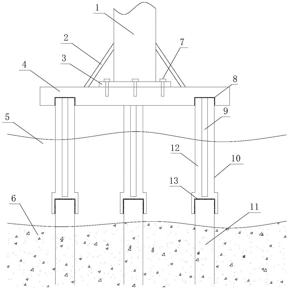
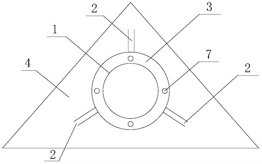
[0025] like figure 1 , figure 2 The schematic structural diagram of the prefabricated composite structure steel pipe pile wind power generation platform of the present invention shown, including steel pipe connecting section 1, steel support 2, connecting plate 3, platform 4, seawater 5, seabed 6, bolt 7, groove 8 , steel frame 9, prefabricated pile 10, foundation steel pile 11, outsourcing concrete 12 and bayonet structure 13.
[0026] The steel pipe connecting section 1 is vertically arranged with the horizontally arranged platform 4, and is located in the middle of the upper surface of the platform 4, wherein the connecting plate 3 is a circular structure, and the annular connecting plate 3 is welded on the bottom of the outer circumference of the steel pipe connecting section 1. , which is fixed on the platform 4 by bolts 4. Three steel supports 2 are evenly arranged on the outer circumference of the steel pipe connecting section 1. One end of the steel supports 2 is connected to the upper surface of the platform 4, and one end is connected to the outer circumference of the steel pipe connecting section 1. The steel supports 2 are arranged at an angle of 45° with the horizontal plane. , which can effectively ensure its fixed stability.
[0027] The platform 4 is a reinforced concrete prefabricated structure with a triangular shape. A circular groove 8 is provided on the lower surface of the bottom of the platform 4. The diameter of the circular groove 8 is slightly larger than the outer diameter of the prefabricated pile 10. The top is inserted into the groove 8 in the lower part of the platform 4 to be clamped and fixed in the structure, so as to support the platform 4. The connection part is grouted, and the elevation is above the water level at the highest tide, which effectively avoids seawater corrosion.
[0028] The cross-section of the prefabricated pile 10 is circular, which is prefabricated by factory processing, and only needs to be installed as a whole at the construction site. . The top end of the prefabricated pile 10 is connected to the platform 4 , and the bottom end is connected to the foundation steel pile 11 . The inner diameter of the bayonet structure 13 at the lower end of the prefabricated pile 10 is slightly larger than the outer diameter of the foundation steel pile 11. When connecting, the top end of the foundation steel pile 11 is clamped in the bayonet of the bayonet structure 13, wherein the bayonet connection is located in the seawater In 5, underwater grouting is used to ensure the strength of the joint.
[0029] The foundation steel pile 11 is a round steel pipe, and its top elevation is above the top elevation of the seabed 6, and is driven into the seabed 6 bearing layer by a piling machine to ensure the firmness of fixation.
[0030] During the specific installation operation, the piling machine drives the foundation steel piles 11 into the seabed 6 to hold the bearing layer for fixation, and hoists the prefabricated piles 10 processed in the factory as a whole to the top elevation position of the foundation steel piles 11 . The mouth structure 13 fixes the prefabricated pile 10 on the upper end of the foundation steel pile 11, and performs underwater grouting treatment at the joint to ensure the installation strength.
[0031] After the prefabricated pile 10 is installed and the lower end connection has a certain strength, the factory prefabricated reinforced concrete platform 4 is hoisted to the elevation of the top surface of the prefabricated pile 10, and the groove 8 of the platform 4 corresponds to the top surface of the prefabricated pile 10 one-to-one. Grouting is used at the connection of groove 8 to strengthen the connection.
[0032] After the reinforced concrete prefabricated platform 4 is installed, the upper steel pipe connection section 1 is connected to the platform 4 through the anchor bolts 7. After the connection is completed, three steel supports 2 are evenly arranged on the outer circumference of the steel pipe connection section 1 to ensure its stability. The wind power generation tower and the steel pipe connecting section 1 are connected correspondingly through flanges.
[0033] The above are only preferred embodiments of the present invention, and do not limit the present invention in any form. Although the present invention has been disclosed above with preferred embodiments, it is not intended to limit the present invention. Technical personnel, within the scope of the technical solution of the present invention, can make some changes or modifications to equivalent examples of equivalent changes by using the technical content disclosed above, but any content that does not depart from the technical solution of the present invention, according to the present invention. The technical essence of the invention Any simple modifications, equivalent changes and modifications made to the above embodiments still fall within the scope of the technical solutions of the present invention.

PUM

no PUM

Description & Claims & Application Information

We can also present the details of the Description, Claims and Application information to help users get a comprehensive understanding of the technical details of the patent, such as background art, summary of invention, brief description of drawings, description of embodiments, and other original content. On the other hand, users can also determine the specific scope of protection of the technology through the list of claims; as well as understand the changes in the life cycle of the technology with the presentation of the patent timeline. Login to view more.

Similar technology patents

Method for breeding high quality chicken with high feather fitness degree

ActiveCN102669049Areduce workloadReduce assay workload
Owner:WENS FOOD GRP CO LTD

Classification and recommendation of technical efficacy words

  • reduce workload
  • Improve efficiency

Hospital gown

InactiveUS7181773B1reduce workloadquickly expose
Owner:WILLIAM BEAUMONT HOSPITAL

Garbage classification prompt garbage can and system based on image recognition

InactiveCN107054936Areduce workloadachieve reuse
Owner:GUANGDONG MATVIEW INTELLIGENT SCI & TECH CO LTD

Intelligent response method and system based on context dialogue semantic recognition

InactiveCN106357942AImprove recommendation hit ratereduce workload
Owner:GUANGZHOU BAILING DATA CO LTD
Why Eureka
Try Eureka