
Deep-buried explosive compaction device

A technology of explosive silting and explosive packs, applied in soil protection, construction, infrastructure engineering, etc., can solve the problems of wasting explosive energy, reducing the effect of replacement, and slow formation of foundation pits, achieving good results and reducing the amount of explosives , the effect of small damage

Active Publication Date: 2015-06-10
陈洪凯 +1
View PDF6 Cites 0 Cited by
  • Summary
  • Abstract
  • Description
  • Claims
  • Application Information

AI Technical Summary

Problems solved by technology

[0003] The method of mechanical desilting and filling method, in which dredging ships such as dredgers are used to remove the silt on the soft soil foundation, and then replace and fill in high-strength crushed stones; the problem with this method is: It has high fluidity and extremely low strength. When the silt is excavated, a large amount of silt will flow back immediately with the water flow, resulting in slow formation of the foundation pit and very low construction efficiency. It is only suitable for shoal embankments with small silt thickness;
[0004] Explosive tamping and silt squeezing method, this method does not remove the silt, directly throws stones into the silt, and then performs explosive ramming on the top surface of the riprap, and uses the pressure generated by the explosion to cause the stones to sink to squeeze out the soft soil The purpose of silt; the problem of this method is that the depth of silt squeezed by a single explosion is only 2-4m, and multiple explosions per unit area need to be frequently carried out to meet the construction requirements. Not only the consumption of explosives is huge, but also the ecology in the water area The environment is seriously damaged and it is not suitable for large-scale promotion;
[0005] Explosive silting method, No. ZL03119314.5, No. ZL97125894.5 and No. ZL201110070978.1 Chinese patents describe this technology in detail. depth, using the cavity produced by the explosion to cause the gravel to slide into the cavity under the action of its own weight, so as to achieve the effect of replacing the silt. Compared with the previous two methods, this method has the advantages of convenient and quick construction and significant economic benefits. At present, It has been widely used in the treatment of coastal soft foundations, but this method also has shortcomings: for example, when embankments are filled longitudinally, the embankment head silt is easy to accumulate and bulge at the embankment head under the action of dumping gravel and explosion loads, affecting And hinder the further filling of the embankment; when the charge explodes, the energy will be transferred to the surroundings, and the silt in the upper area of ​​the explosion cavity will be quickly backfilled, which reduces the effective explosion space volume. From another perspective, this situation is equivalent to wasting a part of the explosion energy. , resulting in insufficient replacement depth; because the upper gravel cannot be filled into the explosion cavity in time when the charge is placed on the outer edge of the dike head for explosion, it will cause the silt in front of the embankment to flow back into the cavity, reducing the replacement effect

Method used


Image

  • Deep-buried explosive compaction device
  • Deep-buried explosive compaction device
  • Deep-buried explosive compaction device

Examples


Embodiment Construction

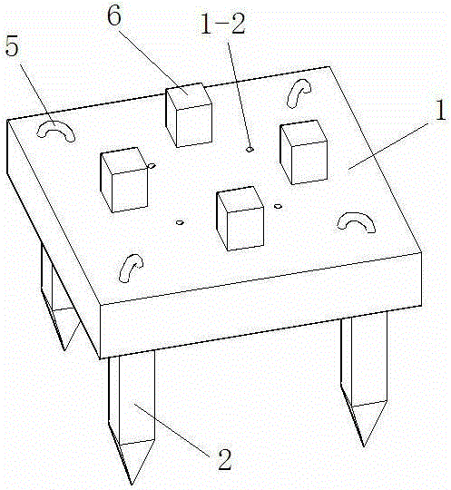
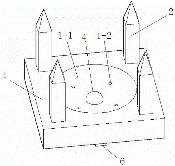
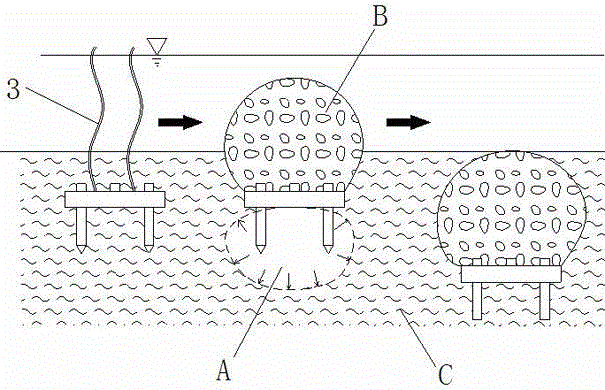
[0018] A deep-buried explosive silting device, the innovation of which is: the deep-buried explosive silting device is composed of a top plate 1, a plurality of pile feet 2, a plurality of suction pipes 3, an explosive package 4 and a suction dredger; The middle part of the lower surface of the top plate 1 is provided with a spherical groove 1-1, and the explosive package 5 is arranged in the middle of the bottom of the spherical groove 1-1; a plurality of pile feet 2 are arranged on the lower surface of the top plate 1, and a plurality of piles The foot 2 is located on the periphery of the spherical groove 1-1; the top plate 1 is provided with a plurality of suction holes 1-2 connecting the bottom of the spherical groove 1-1 and the upper end surface of the top plate 1, and the suction holes at the upper end surface of the top plate 1 The orifice of 1-2 forms a mud outlet, and the orifice of the mud suction hole 1-2 at the bottom of the spherical groove 1-1 forms a mud inlet; ...


PUM


Abstract

A deep-buried explosive compaction device is composed of a top plate, a plurality of pile legs, a plurality of mud suction pipes, a blasting charge and a mud suction machine. A spherical face groove is formed in the middle of the lower end face of the top plate. The blasting charge is arranged in the middle of the groove bottom of the spherical face groove. The pile legs are arranged on the lower end face of the top plate and located on the periphery of the spherical face groove. A plurality of mud suction holes used for communicating the bottom of the spherical face groove with the upper end face of the top plate are formed in the top plate. Mud outlets are formed in openings, in the upper end face of the top plate, of the mud suction holes. Mud inlets are formed in openings, in the groove bottom of the spherical face groove, of the mud suction holes. The mud inlets are located in the periphery of the blasting charge. One ends of the mud suction pipes are connected with the mud outlets in a one-to-one corresponding mode. The other ends of the mud suction pipes are connected with the mud suction machine. The deep-buried explosive compaction device has the technical advantages that the amount of explosives which are used can be effectively decreased, the compaction and replacement effects are very good, and damage to the surrounding ecological environment is small.

Description

technical field [0001] The invention relates to an underwater soft soil foundation explosive silting extrusion technology, in particular to a deep-buried explosive silting extrusion device. Background technique [0002] With the continuous development of cities, precious land resources are becoming increasingly scarce, so people are constantly carrying out land reclamation projects. In land reclamation projects, the biggest difficulty is how to deal with soft soil foundations. At present, the common treatment methods for soft soil foundations are mainly three methods: mechanical drainage and replacement, explosive ramming and explosive squeezing; [0003] The method of mechanical desilting and filling method, in which dredging ships such as dredgers are used to remove the silt on the soft soil foundation, and then replace and fill in high-strength crushed stones; the problem with this method is: It has high fluidity and extremely low strength. When the silt is excavated...

Claims


Application Information

Patent Timeline
IPC IPC(8): E02D3/08
Inventor 陈洪凯董平
Owner 陈洪凯
Learn More