

Shake-proof protection device for building
An earthquake protection and building technology, applied in earthquake protection, building components, etc., can solve the problems of not being able to protect buildings and release seismic waves, and achieve the effect of keeping the ground stable, avoiding shock wave damage, and increasing compressive strength.
- Summary
- Abstract
- Description
- Claims
- Application Information
AI Technical Summary
Problems solved by technology
Method used
Image

Examples
Embodiment 1
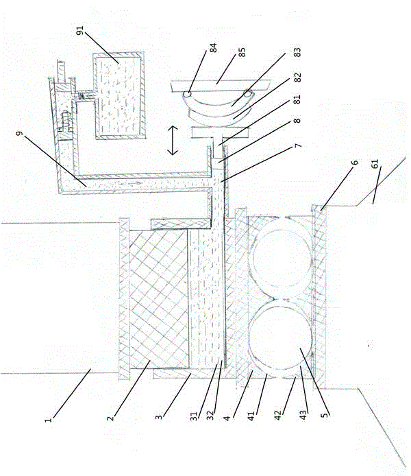
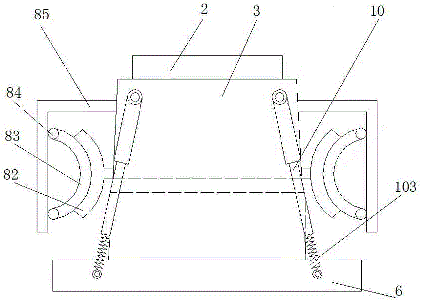
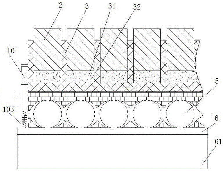
[0023] Embodiment 1. A kind of building anti-seismic protection device, as Figure 1-3 As shown, it includes a support block 2 arranged under the building 1, and a buffer device for releasing shock wave energy in the vertical direction is provided under the support block 2. The buffer device includes a position corresponding to the support block 2. Buffer seat 3, a buffer tank 31 is provided in the buffer seat, buffer liquid 32 is provided in the buffer tank 31, the support block is inserted into the buffer tank 31 and closely matched with the buffer tank 31, and the support block 2 is immersed in the buffer tank 31 In the buffer liquid; the bottom of the buffer seat 3 is provided with a wave-reducing device for releasing shock wave energy in the horizontal direction, and the described wave-reducing device includes an upper base 4 separated up and down and a lower bottom surface for connecting with the building foundation Connected lower base 42, the upper surface of the upper...
Embodiment 2
[0024] Example 2, the buffer solution 32 described in Example 1 can be oil or water.
Embodiment 3
[0025] Example 3, such as figure 1 with figure 2 As shown, the left side or the right side of the buffer tank 31 described in Embodiment 1 is connected with an elastic return device for returning the buffer solution to the initial liquid level, and the elastic return device includes a buffer channel connected to the buffer tank 7. The buffer channel is provided with a return piston 8 and a return push rod 81 connected to the return piston at one end. The other end of the return push rod 81 protrudes from the outside of the buffer channel 7 and is connected to a push rod for pushing the return push rod in the buffer. An elastic piece that moves in the track, one end of the elastic piece is connected with the return push rod, and the other end of the elastic piece is against the limit piece 85 arranged on the outside of the buffer track. The material of the return push rod 81 can be high-temperature alloy steel, and the material of the elastic member can be alloy spring steel....
PUM
 Abstract
Description
Claims
Application Information