A design method of LED collimating lens with double free-form surface

A technology of a collimating lens and a design method, which is applied to lighting and heating equipment, parts of lighting devices, semiconductor devices of light-emitting elements, etc., can solve the problems of increased space and cost of the collimation system, unfavorable modularization and application, etc. , to achieve the effect of improving energy collection rate and saving time

Active Publication Date: 2017-10-20
GUANGDONG INST OF SEMICON IND TECH
View PDF4 Cites 0 Cited by
  • Summary
  • Abstract
  • Description
  • Claims
  • Application Information

AI Technical Summary

Problems solved by technology

In order to achieve uniform illumination of the collimating system, in 2014, Chen et al. [C.Chen and X.Zhang, Design of optical system for collimating the light of an LED uniformly, Vol.31, No.5, May2014, J.Opt. Soc.Am.A] uses the combination of TIR lens and double mirrors to alleviate this problem, but the system uses two mirrors, which greatly increases the space and cost of the collimation system, which is not conducive to the modularization and integration of the system. application

Method used


Image

  • A design method of LED collimating lens with double free-form surface
  • A design method of LED collimating lens with double free-form surface
  • A design method of LED collimating lens with double free-form surface

Examples


Embodiment 1

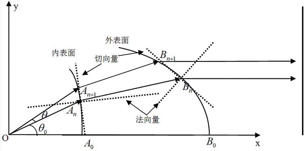
[0055] a) The lens material is polycarbonate (Pc), a highly light-transmitting material, whose refractive index is n=1.59, and the initial value A is introduced 1 Coordinates (12, 0.012), θ=0.001, B 1 The coordinates (25, 0.02), and the step size θ=0.001 are substituted into the iterative relationship in the above step 1, and the trajectory of the obtained coordinate points is as follows Figure 4 shown;

[0056] b) Import the discrete coordinate values ​​of the trajectory obtained above into the proe 3D modeling software, and then automatically fit the above-mentioned coordinate lattice into a curve with a spline curve, and rotate it into a solid model, such as Figure 5 shown;

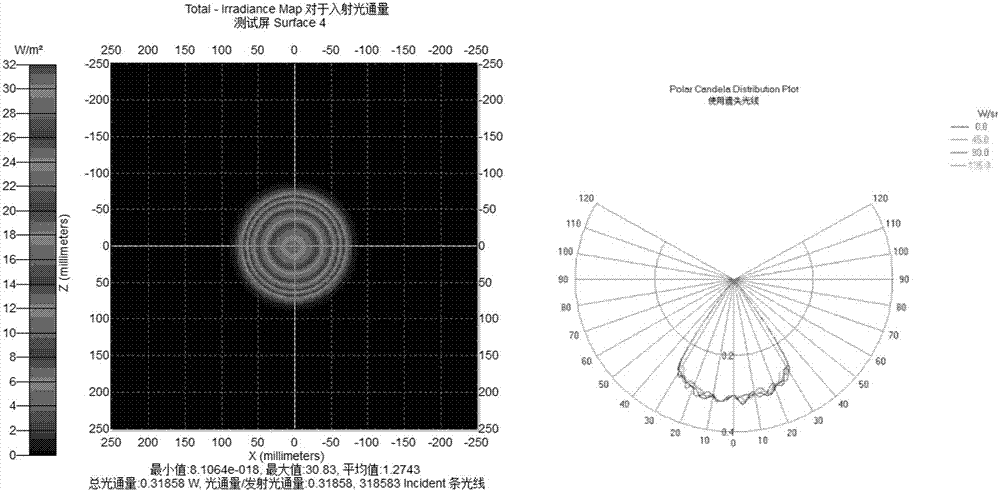
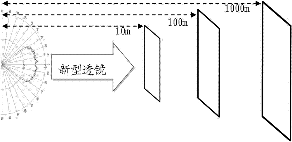
[0057] c) Import the solid model into TracePro optical simulation software for ray tracing simulation, verify and analyze the built model. Such as Figure 6 As shown, the illuminance distribution diagram of the target surface at the distance of 10 meters, 100 meters and 1000 meters from the LED l...

Embodiment 2

[0059] a) The lens material is polycarbonate (Pc), a highly light-transmitting material, whose refractive index is n=1.49, and the initial value A is introduced 1 Coordinates (12, 0.012), θ=0.001, B 1 The coordinates (40, 0.028), and the step size θ=0.001 are substituted into the iterative relationship in the above step 1, and the obtained trajectory coordinates are as follows Figure 7 shown;

[0060] b) Import the discrete coordinate values ​​of the trajectory obtained above into the proe 3D modeling software, and then automatically fit the above-mentioned coordinate lattice into a curve with a spline curve, and rotate it into a solid model, such as Figure 8 shown;

[0061] c) Import the solid model into TracePro optical simulation software for ray tracing simulation, verify and analyze the built model. Such as Figure 9 As shown, the illuminance distribution diagram of the target surface at the distance of 10 meters, 100 meters and 1000 meters from the LED light source...


PUM


Abstract

A design method of a double-free curved surface LED collimating lens comprises the following steps: 1, deducing a double-free curve discrete point coordinate iteration relation; 2, solving free curve track discrete coordinates by using Matlab calculating software; 3, introducing the discrete coordinates into proe 3D modeling software for establishing an entity lens model; 4, tracing light rays of the entity lens model by using TracePro optical simulating software. By the design method, the time can be greatly saved and the light rays can be accurately controlled; through different initial values, collimating lenses with different shapes can be obtained, so that applications to different occasions can be met; the uniformity of illuminance within a very wide range of distance from the lens can reach 90% or above, so that an obvious glaring phenomenon of the conventional collimating lens caused by distribution of most of energy in the center of an irradiation area due to similar Gaussian distribution of a light intensity distribution curve is avoided, and the energy collecting rate is significantly improved.

Description

technical field [0001] The invention relates to the field of LED secondary optical design, in particular to a design method of a double free-form surface LED collimating lens formed by rotating a double free-form curve. Background technique [0002] Semiconductor lighting (LED lighting) is the third light source revolution after incandescent lamps and fluorescent lamps. Due to its outstanding features such as high efficiency, energy saving, environmental protection, long life, and similar point light source, it is one of the most promising high-tech fields in the world in recent years. It has received strong support from major countries and regions in the world. At present, the global LED industry has entered the In the period of rapid development, it is widely used in various indoor and outdoor lighting fields, including flat panel display, digital home appliances, automotive electronics and special lighting, etc. The global LED lighting penetration rate is rapidly increasi...

Claims


Application Information

Patent Timeline
Patent Type & Authority Patents(China)
IPC IPC(8): F21V5/04F21Y115/10
CPCF21V5/04
Inventor 张志清陈志涛许毅钦张康刘晓燕刘宁炀赵维
Owner GUANGDONG INST OF SEMICON IND TECH
Why Eureka
Try Eureka