A countercurrent solution humidity control air treatment device

An air treatment device and solution technology, which is used in air conditioning systems, space heating and ventilation, space heating and ventilation details, etc., can solve the problems of lack of miniaturized and efficient solution dehumidification air treatment devices, device size, capacity limitations, etc., To meet the needs of humidity regulation, the work is simple and reliable

Active Publication Date: 2017-07-18
TSINGHUA UNIV +1
View PDF6 Cites 0 Cited by
  • Summary
  • Abstract
  • Description
  • Claims
  • Application Information

AI Technical Summary

Problems solved by technology

At present, there are air treatment devices that effectively combine solution dehumidification with heat pump circulation. However, due to limitations in size and capacity, such devices are mostly suitable for large-scale buildings. At present, there is still a lack of miniaturized and efficient solution dehumidification air. processing device

Method used


Image

  • A countercurrent solution humidity control air treatment device
  • A countercurrent solution humidity control air treatment device

Examples


Embodiment 1

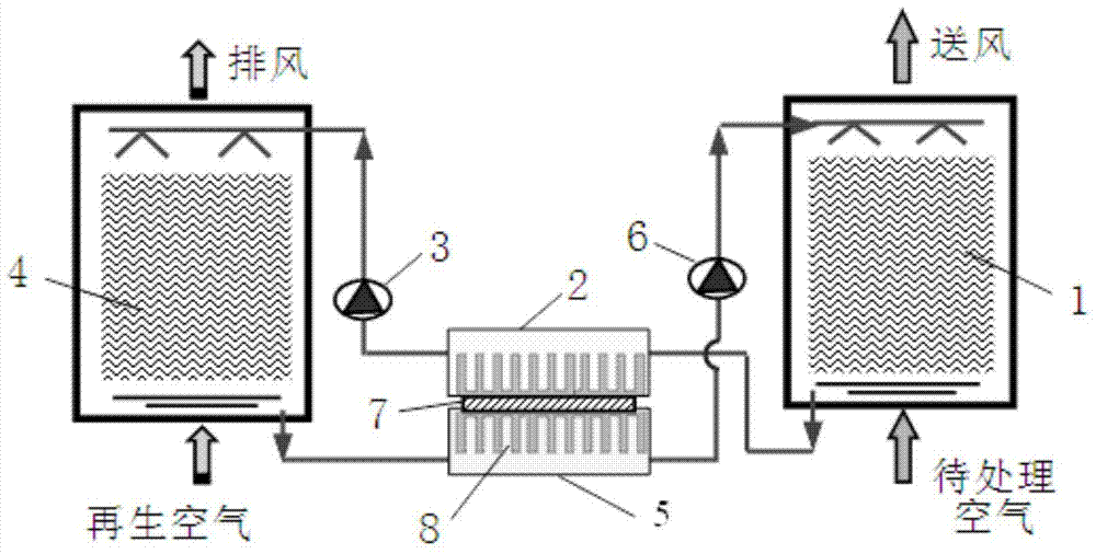
[0016] Such as figure 1 As shown, the countercurrent solution humidity control air treatment device of the present invention includes a dehumidification module 1, a first solution heat exchanger 2, a first solution pump 3, a regeneration module 4, a second solution heat exchanger 5, A second solution pump 6 and a semiconductor refrigeration unit 7; the bottom pipeline of the dehumidification module 1 is connected to one end of the first solution heat exchanger 2, and the other end of the first solution heat exchanger 2 is connected to the regeneration module through the first solution pump 3 4; the bottom pipeline of the regeneration module 4 is connected to one end of the second solution heat exchanger 5, and the other end of the second solution heat exchanger 5 is connected to the top of the dehumidification module 1 through the second solution pump 6, so that the dehumidification module 1, the second A solution heat exchanger 2, a regeneration module 4 and a second solution...

Embodiment 2

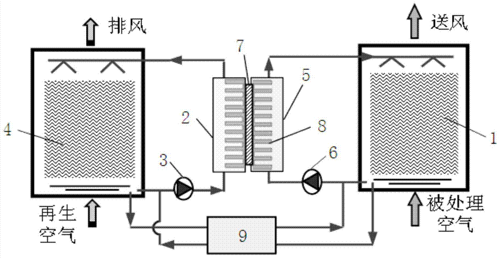
[0024] Such as figure 2As shown, the countercurrent solution humidity control air treatment device of the present invention includes a dehumidification module 1, a first solution heat exchanger 2, a first solution pump 3, a regeneration module 4, a second solution heat exchanger 5, A second solution pump 6, a semiconductor refrigeration unit 7 and a solution heat recovery device 9; the bottom pipeline of the dehumidification module 1 is connected in parallel with the inlet of the second solution pump 6 and the first inlet of the solution heat recovery device 9, the second solution The outlet of the pump 6 is connected to one end of the second solution heat exchanger 5, and the other end of the second solution heat exchanger 5 is connected to the top pipeline of the dehumidification module 1 to form a loop; the bottom pipeline of the regeneration module 4 is connected in parallel to the first The inlet of the solution pump 3 and the second inlet of the solution heat recovery d...


PUM


Abstract

The invention relates to a counter-current solution humidity-conditioning air treatment device. The counter-current solution humidity-conditioning air treatment device comprises a dehumidifying module, a first solution heat exchanger, a first solution pump, a regenerating module, a second solution heat exchanger, a second solution pump and a semiconductor refrigerating unit, wherein the bottom pipeline of the dehumidifying module is connected with one end of the first solution heat exchanger; the other end of the first solution heat exchanger is connected with the top of the regenerating module through the first solution pump; the bottom pipeline of the regenerating module is connected with one end of the second solution heat exchanger; the other end of the second solution heat exchanger is connected with the top of the dehumidifying module, so that the dehumidifying module, the first solution heat exchanger, the regenerating module and the second solution heat exchanger form a loop; the semiconductor refrigerating unit is arranged between the first solution heat exchanger and the second solution heat exchanger; extending fins can be arranged in both the first solution heat exchanger and the second solution heat exchanger. According to the counter-current solution humidity-conditioning air treatment device, the requirement on air humidity treatment can be met; the miniaturization can also be realized.

Description

technical field [0001] The invention relates to the field of heating, ventilating and air-conditioning, in particular to a countercurrent solution humidity-adjusting air treatment device. Background technique [0002] The main task of air conditioning in civil buildings in summer is to cool down and dehumidify, and air dehumidification is an important link to meet the appropriate indoor humidity level and improve the comfort of the indoor environment. Most of the existing dehumidification methods are condensation dehumidification methods, that is, low-temperature cold water, refrigerants and other refrigerants are used to cool the air below the dew point, so that the moisture in the air condenses to complete the dehumidification process. The traditional condensing dehumidification method has problems such as low air supply temperature, energy waste caused by reheating in some cases, condensed water, and air quality. Therefore, seeking new efficient air humidity treatment met...

Claims


Application Information

Patent Timeline
Patent Type & Authority Patents(China)
IPC IPC(8): F24F5/00F24F13/30
CPCF24F3/14F24F5/0042
Inventor 刘晓华张涛陈晓阳
Owner TSINGHUA UNIV
Why Eureka
Try Eureka