
Single-chip high-intensity magnetic field X-axis linear magneto-resistance sensor provided with calibration coil/reset coil

一种磁电阻传感器、磁电阻的技术,应用在磁性传感器领域,能够解决灵敏度差、传感器磁场变化率低、磁场灵敏度低等问题,达到保证测量的精度、提高效率的效果

Active Publication Date: 2015-06-10
MULTIDIMENSION TECH CO LTD
View PDF7 Cites 13 Cited by
  • Summary
  • Abstract
  • Description
  • Claims
  • Application Information

AI Technical Summary

Problems solved by technology

The Hall magnetic sensor obtains different resistance values ​​by depositing a semiconductor film such as indium telluride on the substrate, and deflecting the path of the carrier by the external magnetic field. The advantage is that the Hall magnetoresistive sensor can measure a wide range of magnetic fields. , the disadvantage is that the sensitivity of the magnetic field is low, and it is usually necessary to introduce a flux concentrator to amplify the external magnetic field
The AMR magnetic sensor deposits a single-layer magnetic film on the substrate, changes the magnetic moment direction of the magnetic film through an external magnetic field, thereby changing the resistance at both ends, and its sensing unit and electrodes are prepared as oblique strips, so that the current direction and magnetic field The direction forms a certain angle, so that the direction of the magnetic field can be distinguished. Its advantage is that the sensor unit is simple and only has one layer of thin film. The disadvantage is that the sensor’s magnetic field change rate is low and its sensitivity is poor.

Method used

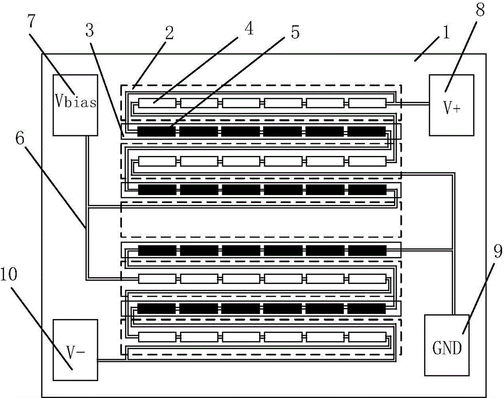

Image

  • Single-chip high-intensity magnetic field X-axis linear magneto-resistance sensor provided with calibration coil/reset coil
  • Single-chip high-intensity magnetic field X-axis linear magneto-resistance sensor provided with calibration coil/reset coil
  • Single-chip high-intensity magnetic field X-axis linear magneto-resistance sensor provided with calibration coil/reset coil

Examples


Embodiment 1

[0068] Figure 4 It is a structure and distribution diagram of a type one calibration coil 70, the calibration coil 70 is a planar coil, including a strip-shaped sensitive straight wire 101 and a reference straight wire 104 connected in series, the sensitive straight wire 101 has a width of Lx1, Its Y-axis center line is arranged along the sensitive magnetoresistive unit string 51, and each section of reference straight wire 104 includes two sub-straight wires 102 and 103, and the sub-straight wires 102 and 103 are connected in parallel and distributed symmetrically along the Y direction. Referring to both sides of the magnetoresistive sensing unit string 41 , the widths of the sub-straight wires 102 and 103 are both Lx2.

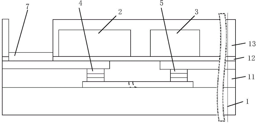
[0069] Figure 5-7 respectively Figure 4 Shown is a cross-sectional view of an X-axis magnetoresistive sensor comprising a type one calibration coil 70, wherein, Figure 5 Among them, the planar calibration coil is located on the substrate 1 and below t...

Embodiment 2

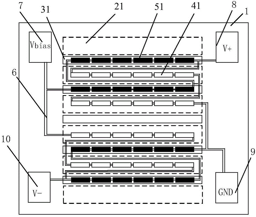
[0078] Figure 14 It is a structural diagram of the type two planar calibration coil 80 on a single-chip X-axis linear magnetoresistive sensor with a high-intensity magnetic field. The type two planar calibration coil 80 includes two straight wires, that is, a reference straight wire 105 and a sensitive straight wire 106, respectively located in the shield The gap between the shield 21 and the attenuator 31, and the reference straight wire 105 has a wider width and is located on the side close to the shield 21, and the sensitive straight wire 106 is narrower and is located on the side near the attenuator 31, and The sensitive straight wire 106 and the reference straight wire 105 are connected in series.

[0079] Figure 15 It is a cross-sectional view of a type two planar calibration coil 80 on a single-chip X-axis linear magnetoresistive sensor with a high-intensity magnetic field. Wherein, the reference straight wire 105 and the sensitive straight wire 106 are located at t...

Embodiment 3

[0083] Figure 19 It is a distribution diagram of the type three-plane calibration coil 81 on the high-intensity magnetic field single-chip X-axis magnetoresistive sensor. The type three-plane calibration coil 81 includes a sensitive straight wire 107 and a reference straight wire 108, both of which are connected in series, wherein the reference straight wire The wire 108 corresponds to the shield 21, the sensitive straight wire 107 corresponds to the attenuator 31, and the reference straight wire 108 and the sensitive straight wire 107 are elongated, which are respectively connected to the attenuator. 31 coincides with the Y-axis centerline of the shield 21, and the width of the sensitive straight wire 107 is smaller than the width of the reference straight wire 108.

[0084] Figure 20 It is a cross-sectional view of the type three-plane calibration coil 81 on the high-intensity magnetic field single-chip X-axis magnetoresistive sensor, and the reference straight wire 108 a...


PUM


Abstract

A single-chip high-intensity magnetic field X-axis linear magneto-resistance sensor provided with a calibration coil / reset coil comprises a high-intensity magnetic field single-chip reference bridge type X-axis resistance sensor and the calibration coil / reset coil, wherein the calibration coil is a planar coil, the reset coil is a planar or three-dimensional coil, the planar calibration coil and the planar reset coil can be located above a substrate and under a magneto-resistance sensing unit, between the magneto-resistance sensing unit and a soft magnetic flux guider, above the soft magnetic flux guider or at the gap position, the soft magnetic flux guider and the magneto-resistance sensing unit are winded with the three-dimensional rest coil, and the calibration coil and the reset coil respectively produce calibration magnetic fields parallel to pinning layer direction and even reset magnetic fields in free layer direction at the position of a magneto-resistance unit. Calibration and magnetic-state reset of the single-chip X-axis linear magneto-resistance sensor can be achieved by controlling the current of the calibration coil / reset coil, and the single-chip high-intensity magnetic field X-axis linear magneto-resistance sensor ahs the advantages of being efficient, quick to use and convenient to operate.

Description

technical field [0001] The invention relates to the field of magnetic sensors, in particular to a high-intensity magnetic field X-axis linear magnetoresistance sensor with a calibration coil / reset coil on a single chip. Background technique [0002] Silicon magnetic sensors mainly include Hall magnetic sensors, AMR magnetic sensors, and GMR magnetic sensors. The Hall magnetic sensor obtains different resistance values ​​by depositing a semiconductor film such as indium telluride on the substrate, and deflecting the path of the carrier by the external magnetic field. The advantage is that the Hall magnetoresistive sensor can measure a wide range of magnetic fields. , its disadvantage is that the sensitivity of the magnetic field is low, and it is usually necessary to introduce a flux concentrator to amplify the external magnetic field. The AMR magnetic sensor deposits a single-layer magnetic film on the substrate, changes the magnetic moment direction of the magnetic film th...

Claims


Application Information

Patent Timeline
Patent Type & Authority Applications(China)
IPC IPC(8): G01R33/09
CPCG01R33/0017G01R33/098G01R33/0011G01R33/0094G01R33/0076G01R33/09
Inventor 詹姆斯·G·迪克周志敏
Owner MULTIDIMENSION TECH CO LTD
Learn More