Supercharge Your Innovation With Domain-Expert AI Agents!

Phase compensating method for longitudinal differential protective current of YNd1 wired transformer

A technology of current phase compensation and longitudinal differential protection, which is applied in the direction of emergency protection circuit devices and electrical components, can solve the problems of not being able to adapt to the wiring group, wiring combination mode, and wiring mode limitations, and achieve small changes in the secondary circuit , easy to achieve effect

Inactive Publication Date: 2015-06-10
STATE GRID CORP OF CHINA +2
View PDF3 Cites 2 Cited by
  • Summary
  • Abstract
  • Description
  • Claims
  • Application Information

AI Technical Summary

Problems solved by technology

However, at present, the differential protection current software phase compensation method of various transformer protection manufacturers can only adapt to the transformer wiring groups and their wiring combinations of YNd11, YNd1 and YNyn12, and cannot adapt to other wiring groups and wiring combinations.
Chinese patent application 201210452816.9 proposes a YNd1 transformer longitudinal differential protection current phase compensation method, but it still has limitations in wiring methods in practical applications, so more alternatives are needed

Method used


Image

  • Phase compensating method for longitudinal differential protective current of YNd1 wired transformer
  • Phase compensating method for longitudinal differential protective current of YNd1 wired transformer
  • Phase compensating method for longitudinal differential protective current of YNd1 wired transformer

Examples


Embodiment Construction

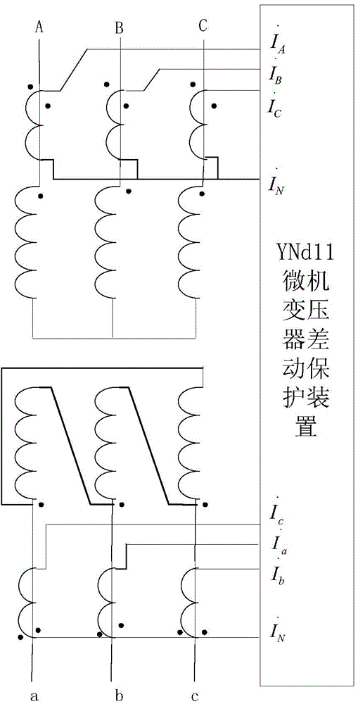
[0017] In the embodiment of the present invention, the connection mode of the YNd1 connection transformer is transformed as follows:

[0018] 1. The phase relationship between YNd1 connection transformer and YNd7 series connection transformer

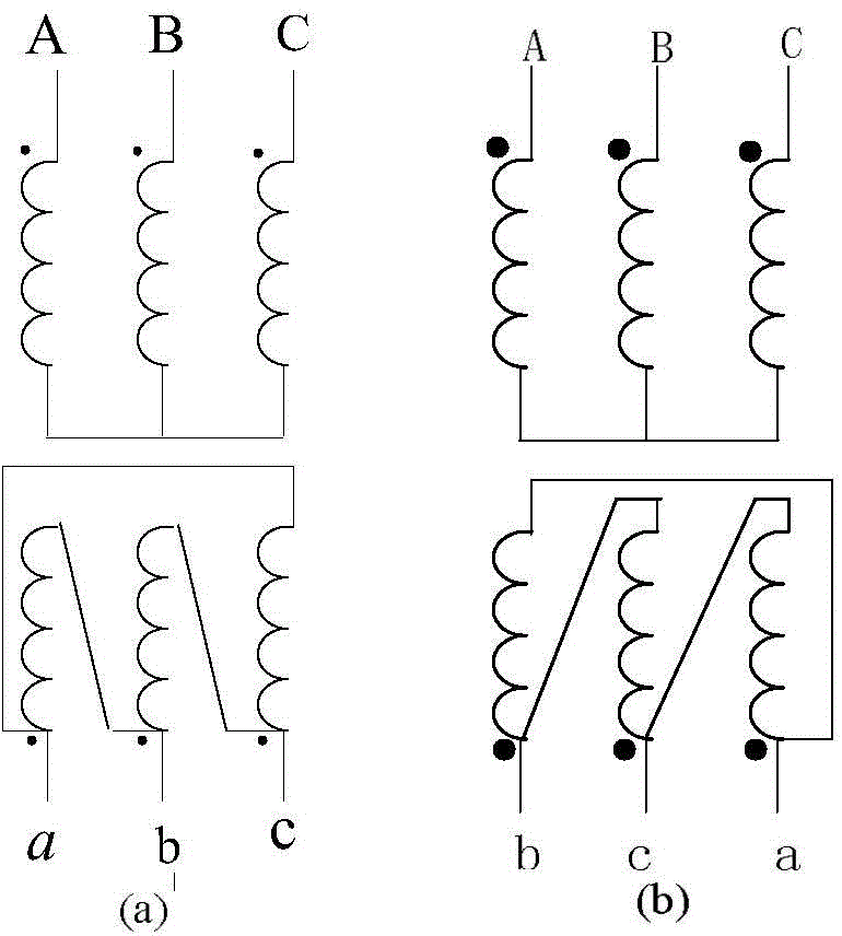
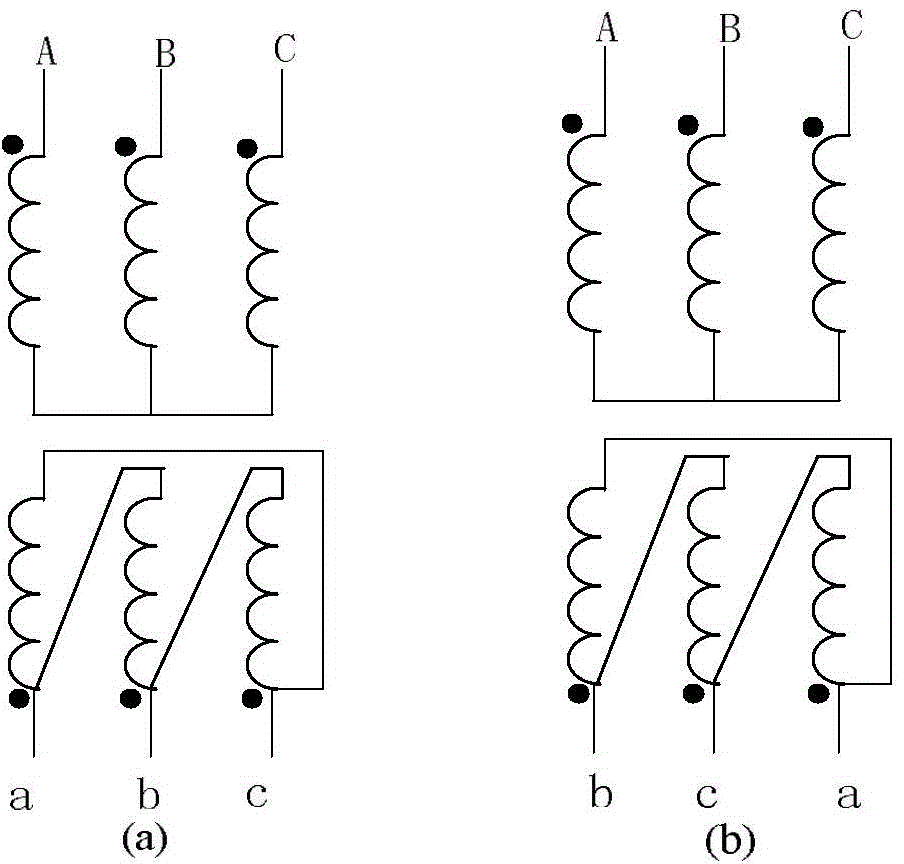
[0019] YNd1 connection transformer wiring diagram see figure 1 a). Because the three-phase voltages on the high-voltage side and low-voltage side of the YNd1 transformer are symmetrical, only one line voltage comparison is required, so there is Ahead 30 degrees. See the wiring diagram of YNd7 wiring transformer figure 1 b), in the same way YNd7 transformer Ahead 210 degrees. We put the YNd1 transformer With YNd7 transformer Consider the same phase, compare YNd1 transformer and YNd7 transformer low-voltage side The relationship between the YNd7 transformer low-voltage side Lag YNd1 on the low-voltage side of the transformer 180 degrees, that is, the phase currents on the low-voltage side of the YNd7 transformer and YNd1 transforme...


PUM


Abstract

The invention belongs to a protective relaying control technology of power transmission and distribution networks, and relates to microcomputer-controlled phase compensating method for a longitudinal differential protective current of an YNd1 wired transformer. A specific wiring method thereof is as follows: 1) remaining each current phase that connects each phase of current of a TA secondary winding on a Y side of the YNd1 transformer to a differential protection of a YNd11 wired transformer unchanged; 2) reversely connecting a b-phase current, a c-phase current and an a-phase current of a TA secondary current on a d side of the YNd1 transformer respectively to an a-phase current loop, a b-phase current loop and a c-phase current loop on a d side of a protective device of the YNd11 transformer; 3) using a software phase compensation of the protective device of the YNd11 transformer to finish the differential protective phase compensation of the YNd1 wired transformer. The phase compensating method for the longitudinal differential protective current of the YNd1 wired transformer is able to finish the differential protective current phase compensation of the YNd1 wired transformer; and the phase compensating method for the longitudinal differential protective current of the YNd1 wired transformer is simple in theories, and convenient in implementations.

Description

Technical field [0001] The invention belongs to the relay protection control technology of a power transmission and distribution network, and relates to a YNd1 connection transformer longitudinal linkage differential protection current phase compensation method used for microcomputer control. Background technique [0002] Since the current on each side of the transformer may be inconsistent in phase, the transformer longitudinal differential protection (referred to as the transformer differential protection) needs to perform current phase compensation. There are two methods for transformer differential protection current phase compensation: 1. Traditional hardware phase shift: for example, YNd11 transformer Y-side current transformer (TA) secondary winding adopts triangular d-11 connection, and d-side TA secondary winding adopts Star Y-12 wiring; 2, software phase shift: that is, use software programs and calculation formulas to perform current phase shift to complete phase compe...

Claims


Application Information

Patent Timeline
IPC IPC(8): H02H7/045
Inventor 李静汤大海施伟成
Owner STATE GRID CORP OF CHINA
Features
  • R&D
  • Intellectual Property
  • Life Sciences
  • Materials
  • Tech Scout
  • Unparalleled Data Quality
  • Higher Quality Content
  • 60% Fewer Hallucinations
Learn More