
Infrared thermal imaging set

A technology of infrared thermal imaging and equipment, applied in the infrared field, can solve the problems of limiting the scope of application of infrared thermal imaging equipment and single function, and achieve real-time observation and temperature measurement functions, wide application range and rich functions

Active Publication Date: 2015-06-10
HANGZHOU HIKVISION DIGITAL TECH
View PDF5 Cites 6 Cited by
  • Summary
  • Abstract
  • Description
  • Claims
  • Application Information

AI Technical Summary

Problems solved by technology

[0003] Usually, the temperature-measuring infrared thermal imaging device can only realize the temperature measurement function of different points on the surface of the measured object, while the observation-type infrared thermal imaging device can only realize the observation function, that is, the measured object is displayed in the form of an observation image. The difference in temperature at different points on the surface
[0004] It can be seen that the existing infrared thermal imaging equipment has a single function, which limits the scope of application of infrared thermal imaging equipment

Method used


Image

  • Infrared thermal imaging set
  • Infrared thermal imaging set
  • Infrared thermal imaging set

Examples


Embodiment Construction

[0017] In order to make the technical solution of the present invention more clear and understandable, the solution of the present invention will be further described in detail below with reference to the accompanying drawings and examples.

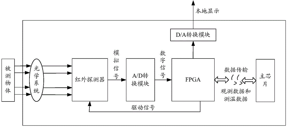
[0018] figure 1 It is a schematic diagram of the composition and structure of an embodiment of the infrared thermal imaging device of the present invention. Such as figure 1 As shown, it includes: Field Programmable Gate Array (FPGA, Field Programmable Gate Array) and the main chip. In addition, it can further include: optical system, infrared detector, A / D conversion module, D / A conversion module, flash memory ( FLASH) and Double Data Rate Synchronous Dynamic Random Access Memory (DDR, Double Data Rate Synchronous Dynamic Random Access Memory), etc., to simplify the drawings, FLASH and DDR are not shown.

[0019] The infrared detector converts the infrared radiation emitted by the object under test (heat radiator) into the optical syst...


PUM


Abstract

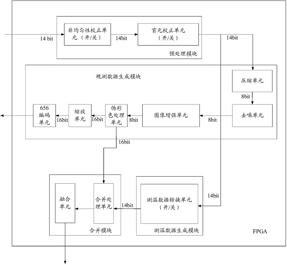
The invention discloses an infrared thermal imaging set comprising a FPGA (field programmable gateway array) and a main chip. The FGPA is used for preprocessing original data received, generating observation data and temperature measuring data according to the preprocessed data and transmitting them to the main chip. The main chip is used for finishing observation and temperature measurement according to the received observation data and temperature measuring data. The infrared thermal imaging set has the temperature measuring function and the observation function, has richer functions and accordingly is more widely applicable.

Description

technical field [0001] The invention relates to infrared technology, in particular to an infrared thermal imaging device. Background technique [0002] Existing infrared thermal imaging equipment can be divided into two types according to their functions, namely temperature measuring type and non-temperature measuring type, and the non-temperature measuring type can also be called observation type. [0003] Usually, the temperature-measuring infrared thermal imaging device can only realize the temperature measurement function of different points on the surface of the measured object, while the observation-type infrared thermal imaging device can only realize the observation function, that is, the measured object is displayed in the form of an observation image. The difference in temperature at different points on a surface. [0004] It can be seen that the existing infrared thermal imaging equipment has a single function, thus limiting the scope of application of the infrar...

Claims


Application Information

Patent Timeline
Patent Type & Authority Applications(China)
IPC IPC(8): H04N5/33H04N5/232H04N9/04G01J5/10
Inventor 林克荣葛路烨
Owner HANGZHOU HIKVISION DIGITAL TECH
Learn More