Power generation control device
A control device and power generation control technology, which is applied in the direction of control device, power consumption device, circuit device, etc., can solve the problem of inability to obtain energy balance and other problems, and achieve the effect of improving operation efficiency
- Summary
- Abstract
- Description
- Claims
- Application Information
AI Technical Summary
Problems solved by technology
Method used
Image
Examples
no. 1 approach 》
[0058]
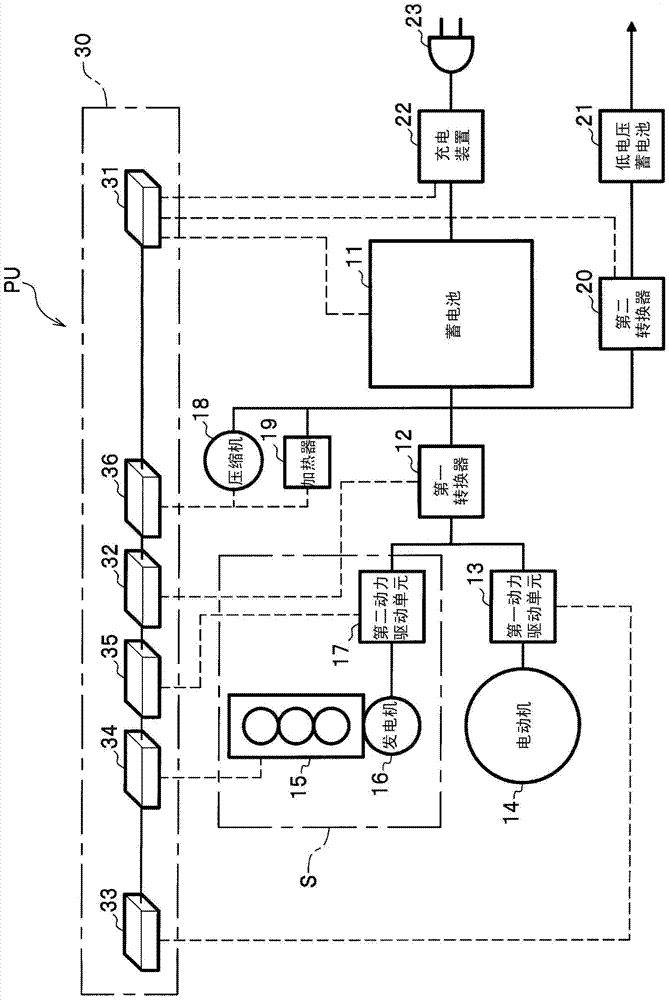
[0059] figure 1 It is a block diagram showing the overall configuration of the power unit PU of the vehicle.
[0060] Such as figure 1 As shown, the power unit PU mounted on a vehicle (hybrid vehicle) includes a battery 11, a first converter 12, a first power drive unit 13, an electric motor 14, an internal combustion engine 15, a generator 16, a second power drive unit 17, an electric motor A compressor 18 , an electric heater 19 , a second converter 20 , a low-voltage battery 21 , a charging device 22 , an external charging plug 23 and a control device 30 . Here, the internal combustion engine 15 , the generator 16 , and the second power drive unit 17 constitute an auxiliary power unit S that generates electric power from the driving force of the internal combustion engine 15 .
[0061] The storage battery 11 is, for example, a lithium ion (Li-ion) secondary battery, and can be charged and discharged.
[0062] One side of the first converter 12 is connected t...
no. 2 approach 》
[0198]
[0199] Next, the power unit PU of the second embodiment will be described. The overall structure of the power unit PU of the second embodiment is the same as that of the power unit PU of the first embodiment (refer to figure 1 ) are the same, so the explanation is omitted.
[0200]
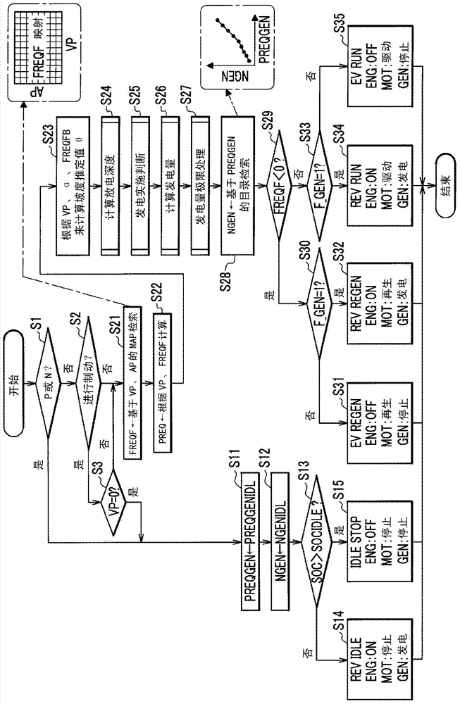
[0201] Next, the operation mode determination process for the power unit PU of the second embodiment (refer to figure 2 )Be explained. The control device 30 of the power unit PU of the first embodiment and the second embodiment is figure 2 In step S27, limit processing (power generation amount limit processing) is performed on the generator power generation output PREQGEN calculated in step S26. Here, the power generation amount limit processing in the first embodiment is Figure 6 "Power generation amount limit processing (upper limit value)" shown. On the other hand, the power generation limit processing in the second embodiment is Figure 9 The "power generation amount lim...
no. 3 approach 》
[0223]
[0224] Next, the power unit PU of the third embodiment will be described. The overall structure of the power unit PU of the third embodiment is the same as that of the power unit PU of the first embodiment (refer to figure 1 ) are the same, so the explanation is omitted.
[0225]
[0226] Next, use Figure 11 , the operation mode determination process of the power unit PU according to the third embodiment will be described. Figure 11 It is a flowchart of the operation mode determination process of the power unit PU in the third embodiment.
[0227] The operation mode determination process of the first embodiment (refer to figure 2 ) calculates the amount of power generated by the generator 16, that is, the generator power generation output PREQGEN (refer to step S26), and performs limit processing on the generator power generation output PREQGEN (refer to step S27), and then obtains the rotation speed of the internal combustion engine 15, that is, the genera...
PUM
 Abstract
Description
Claims
Application Information
 - R&D
- Intellectual Property
- Life Sciences
- Materials
- Tech Scout
- Unparalleled Data Quality
- Higher Quality Content
- 60% Fewer Hallucinations
Browse by: Latest US Patents, China's latest patents, Technical Efficacy Thesaurus, Application Domain, Technology Topic, Popular Technical Reports.
© 2025 PatSnap. All rights reserved.Legal|Privacy policy|Modern Slavery Act Transparency Statement|Sitemap|About US| Contact US: help@patsnap.com


