drive unit

A driving device and motor technology, applied in the direction of electromechanical devices, circuit devices, electric components, etc., can solve the problems of disconnection volume and increase, and achieve the effect of saving space

Active Publication Date: 2018-08-10
FUJI KK
View PDF7 Cites 0 Cited by
  • Summary
  • Abstract
  • Description
  • Claims
  • Application Information

AI Technical Summary

Problems solved by technology

The purpose of the technology disclosed in this specification is to solve the problems of disconnection and volume increase

Method used


Image

  • drive unit
  • drive unit
  • drive unit

Examples


Embodiment

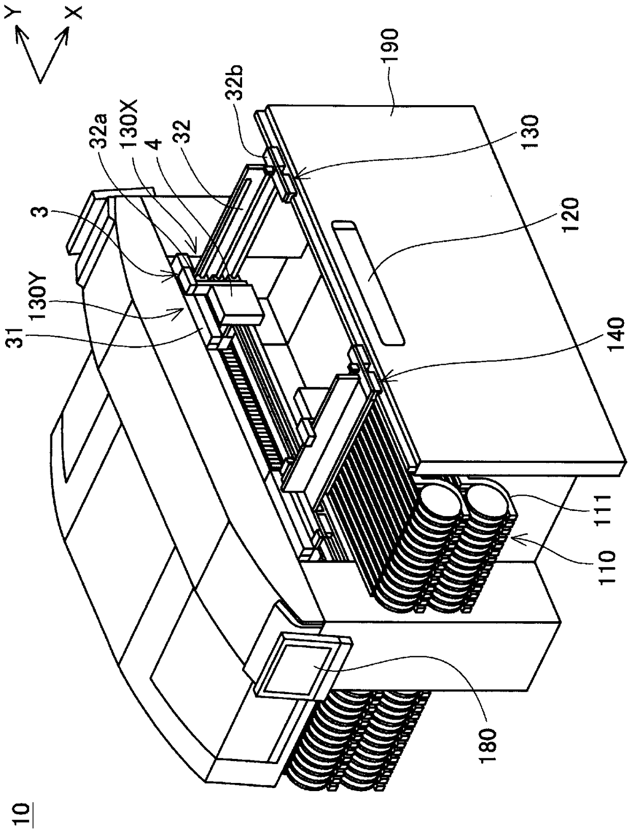
[0024] Hereinafter, a mounting machine used when forming an integrated circuit on a circuit board will be described with reference to the drawings. The integrated circuits on the circuit board are transported and formed in the order of a solder printer, a mounting machine, and a reflow oven. The solder printing machine prints solder paste on the mounting positions of the electronic components on the circuit board. The mounting machine mounts electronic components at mounting positions on a circuit board on which solder paste is printed. A reflow oven solders electronic components to a circuit board by applying heat treatment to the circuit board.

[0025] Such as figure 1 As shown, the mounting machine 10 includes two modules arranged adjacently, and each module has a common structure. figure 1 Indicates that the outer cover plate of one of the two modules has been removed. Each module includes a component supply device 110 , a substrate transfer device 120 , two component...


PUM


Abstract

A drive device comprising: a fixed part; a first communicator disposed on the fixed part; a first movable part configured to be movable in a first direction relative to the fixed part; a second communicator disposed on the above-mentioned The first movable part is configured to be able to perform wireless communication with the above-mentioned first communicator; and the non-contact power supply device is configured to transfer from the power transmitting part provided on the above-mentioned fixed part to the receiving part provided on the above-mentioned first movable part in a non-contact manner. The Ministry of Electricity supplies electricity.

Description

technical field [0001] The technology disclosed in this specification relates to a driving device that drives a movable portion by a single shaft or multiple shafts. In particular, the technology disclosed in this specification relates to a drive device provided in a substrate working machine. The board working machine described here performs predetermined work on a board, and includes, for example, a solder printer for printing solder paste on a circuit board, a mounting machine for mounting electronic components on a circuit board (also called a surface mount machine or a mounter), Board inspection machines, etc. that inspect circuit boards on which electronic components are mounted. Background technique [0002] The substrate working machine is provided with a drive device that drives a movable part with a single shaft or multiple shafts. For example, a mounting machine as an example of a board working machine includes a driving device that drives a movable portion on w...

Claims


Application Information

Patent Timeline
Patent Type & Authority Patents(China)
IPC IPC(8): H05K13/04H02K41/03
CPCH02K11/0094H02K41/031H02K11/21H02K11/22H02J50/80H05K13/0406
Inventor 神藤高广野村壮志长坂伸夫广田重元石浦直道泷川慎二今寺泰章
Owner FUJI KK
Why Eureka
Try Eureka