
Motor commutation head milling surface processing apparatus use method

A processing device and face milling technology, which is applied to positioning devices, metal processing equipment, metal processing machinery parts, etc., to achieve high positioning and processing accuracy, improve work efficiency, and simple structure

Inactive Publication Date: 2015-06-17
WUXI SAINENG MICRO MOTOR
View PDF0 Cites 0 Cited by
  • Summary
  • Abstract
  • Description
  • Claims
  • Application Information

AI Technical Summary

Problems solved by technology

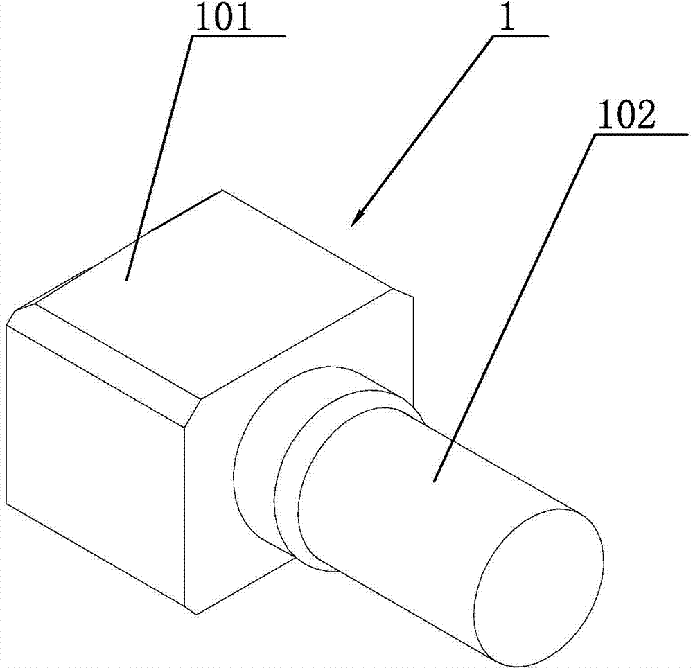
like figure 1 As shown, the end face 101 of the reversing head 1 needs to be processed, and it is especially suitable for the processing of such workpieces with high flatness and precision requirements. However, the processing method of the planar milling requires precise positioning to ensure the accuracy of the milled surface. Flatness and processing accuracy, so there is an urgent need for the method of using the motor commutation head milling device

Method used


Image

  • Motor commutation head milling surface processing apparatus use method
  • Motor commutation head milling surface processing apparatus use method
  • Motor commutation head milling surface processing apparatus use method

Examples


Embodiment Construction

[0017] The specific implementation manner of the present invention will be described below in conjunction with the accompanying drawings.

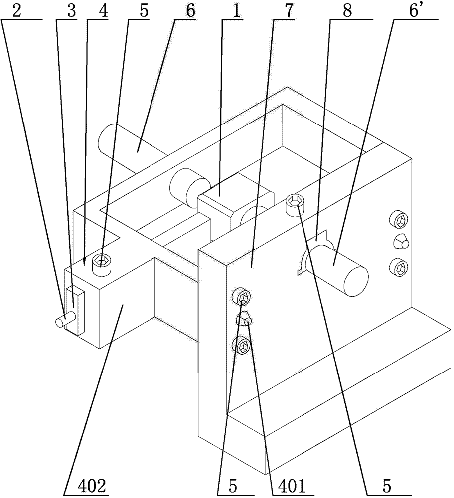
[0018] Such as figure 2 As shown, the method of using the motor reversing head milling processing device includes a mounting seat 4, and the two ends of the mounting seat 4 are provided with tapered bumps 401, and the mounting seat 4 is inserted into the fixed plate 7 through the above-mentioned tapered bumps 401 And fixedly connected by the lock nut 5, the fixed plate 7 is "L" shape. One side of the mounting base 4 extends outward to form a boss 402, and a through groove (not shown in the figure) is opened in the boss 402, and the positioning plate 3 is installed in the groove and locked by the lock nut 5. One side of the plate 3 also extends outwards to form a handle 2, which is cylindrical. On the side perpendicular to the boss 402 of the mounting seat 4, there is also a first positioning rod mounting hole, and the first positioning ...


PUM


Abstract

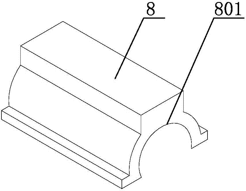
The present invention relates to a motor commutation head milling surface processing apparatus use method, which comprises that: 1, a fixed plate is fixedly connected to an operating table; 2, the locking nut on a boss is loosened, a positioning plate slides in a through groove through a handle, and the positioning plate is locked through the locking nut so as not to move after the positioning plate moves to the designated position; 3, one surface of the commutation head bears against the positioning plate, a first positioning rod rotates so as to bear against the other surface of the commutation head, and the round end of the commutation head extends into a first hemicycle opening and is connected with a second hemicycle opening so as to form a complete round hole; 4, a second positioning rod further extends into the complete round hole and bears against the round end of the commutation head, and then the first positioning rod rotates so as to make the commutation head be positioned between the first positioning rod and the second positioning rod; and 5, the commutation head is subjected to milling processing. According to the present invention, advantages of simple structure, easy installation, time saving, labor saving, high positioning precision, and substantial work efficiency improving are provided.

Description

technical field [0001] The invention relates to a tooling structure, in particular to a method for using a motor reversing head surface milling device. Background technique [0002] At present, in the machinery processing industry equipment, the surface of parts needs to be processed in order to ensure their reference during processing. This processing method is called plane milling, or face milling for short. Such as figure 1 As shown, the end face 101 of the reversing head 1 needs to be processed, and it is especially suitable for the processing of such workpieces with high flatness and precision requirements. However, the processing method of the planar milling needs to be precisely positioned to ensure the accuracy of the milled surface. Flatness and machining accuracy, so there is an urgent need for a method involving the use of a motor reversing head milling device. Contents of the invention [0003] In view of the above-mentioned existing problems, the applicant h...

Claims


Application Information

Patent Timeline
Patent Type & Authority Applications(China)
IPC IPC(8): B23C9/00B23Q3/00B23C3/00
CPCB23C9/00B23C3/00B23Q3/06
Inventor 过晓杰
Owner WUXI SAINENG MICRO MOTOR
Learn More