Ratchet wheel type thread initial point resetting device

A technology of reset device and starting point, which is applied in the field of ratchet thread starting point reset device, can solve the problems of heavy workload, heavy maintenance, waste oil cylinders, etc., and achieve the effects of reducing workload, reliable work and reducing cost

Active Publication Date: 2015-06-17
NINGBO SHUANGLIN MOULD CO LTD
View PDF5 Cites 3 Cited by
  • Summary
  • Abstract
  • Description
  • Claims
  • Application Information

AI Technical Summary

Problems solved by technology

The manual reset method has low efficiency and human negligence. If the mold is closed without reset, waste products will be generated. In addition, there must be someone on duty during production and the workload is heavy, which is not suitable for the large-scale production requirements of unattended one person and multiple machines.
The oil cylinder method adopts a positioning pin in the mold that is controlled and driven by an oil cylinder. Before the product is demoulded and the threaded core rotates, the oil cylinder first pulls the positioning pin out of the threaded core, and the threaded core is then rotated to pull the core out and the mold is closed. When the rotating threaded core meets the positioning pin, the oil cylinder will insert the positioning pin into the threaded core to reset the threaded core; The reliability of the reset method is low, the amount of maintenance is large, and the maintenance cost is high; therefore, the prior art has the problems and deficiencies of heavy workload, low efficiency, high scrap rate, high cost, and inability to meet the requirements of large-scale production

Method used


Image

  • Ratchet wheel type thread initial point resetting device
  • Ratchet wheel type thread initial point resetting device
  • Ratchet wheel type thread initial point resetting device

Examples


Embodiment Construction

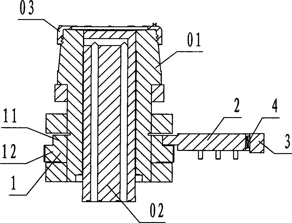
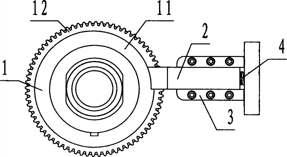
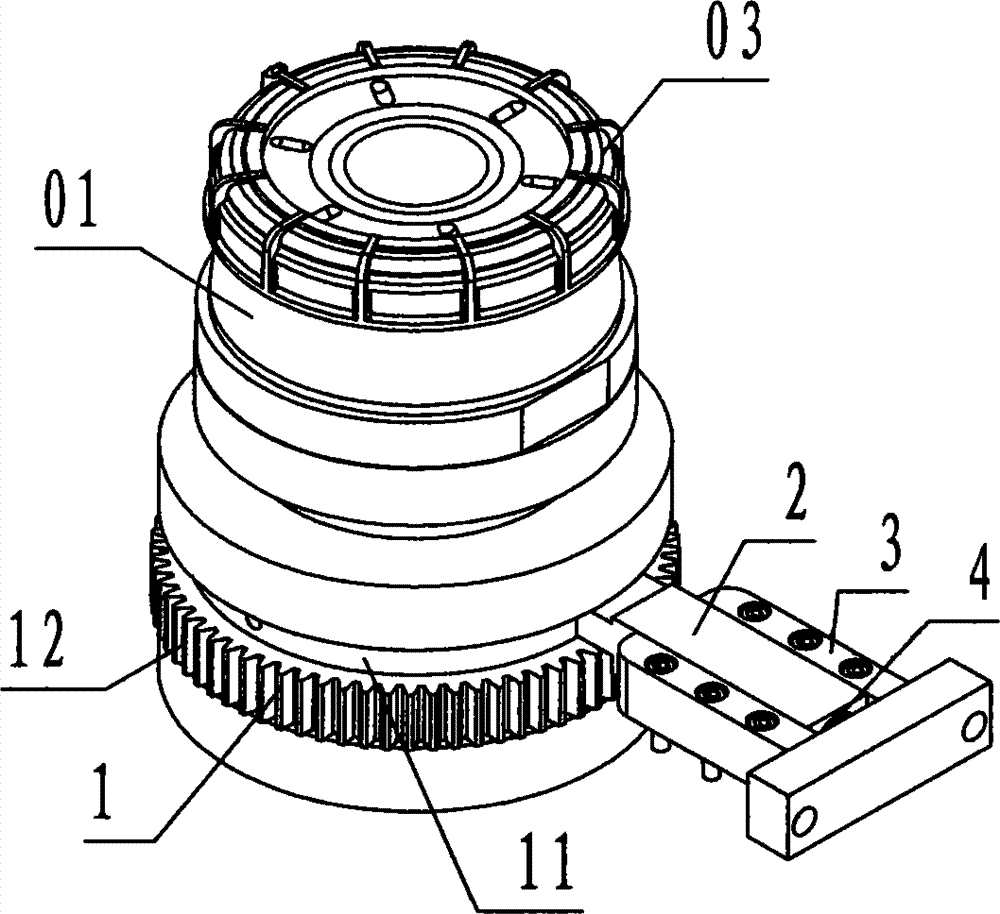
[0022] refer to Figure 1 ~ Figure 3 , a ratchet-type thread starting point reset device of the present invention includes a ratchet double wheel 1, a pawl 2, a chute 3, and a spring 4, wherein: the ratchet double wheel 1 is a small upper and a lower large cylinder Step-shaped steel member, the center of the ratchet double wheel 1 is provided with a circular through hole in the up and down direction called the shaft hole, and the outer edge of the upper small step of the ratchet double wheel 1 is a single stop that rotates counterclockwise. The ratchet wheel 11 of tooth, the outer edge of the bottom big step of ratchet duplex wheel 1 is the gear 12 of cylindrical spur tooth;

[0023] The ratchet 2 is a rectangular block-shaped steel member, the left part of the ratchet 2 is called the claw head, the left end surface of the claw head is an arc-shaped arc surface, and the front and rear sides of the right part of the ratchet 2 are The flanges with protruding, rectangular cross-...


PUM


Abstract

The invention discloses a ratchet wheel type thread initial point resetting device. The ratchet wheel type thread initial point resetting device comprises a ratchet twin wheel (1), a pawl (2), sliding chutes (3), and a spring (4), wherein a single-tooth ratchet wheel counterclockwise rotating to be locked is arranged at the upper part of the ratchet twin wheel; a cylindrical straight-tooth gear is arranged at the lower part of the ratchet twin wheel; a pawl head is arranged at the left end of the pawl; sliding rails are arranged on the front side and the rear side of the right part of the pawl; rail grooves matched with the sliding rails of the pawl are formed in the sliding chutes; the ratchet twin wheel fixedly sleeves the lower part of a rotary mold core; the sliding chutes are fixedly connected with a movable mold supporting plate; the spring is propped against the right end of the pawl; the pawl head of the pawl is in elastic sliding contact with the outer edge of the ratchet wheel; in the demolding process, the rotary mold core is rotated clockwise for any circles while the ratchet wheel is not fastened by the pawl till the thread product is demolded; in the resetting process, the rotary mold core is rotated counterclockwise, the ratchet wheel is fastened by the pawl in a range of a circle, and then the thread initial point is reset. With adoption of the technical scheme, the thread initial point of the threaded injection mold is reset, so as to reduce the workload, improve the efficiency, eliminate wastes and lower the cost; the ratchet wheel type thread initial point resetting device can meet the large-scale production requirement.

Description

technical field [0001] The invention relates to a thread core-pulling device for an injection mold, in particular to a ratchet-type thread start point reset device for a thread type injection mold with a positioning requirement for the thread start point of a product. Background technique [0002] Thread injection molding products are divided into single-head multi-turn thread structure and single-turn multi-start thread structure. This article involves injection molds for single-head multi-turn thread structure injection molding products. Refer to Figure 4 . Threaded injection molded products with higher requirements must adopt spiral demoulding. Spiral demoulding usually uses a motor, oil motor or oil cylinder located outside the mold to drive the threaded rotating core inside the mold through a reduction gear or rack to move along the axial direction. Rotate out threaded injection molded products. After demoulding, the orientation of the thread starting point of the thr...

Claims


Application Information

Patent Timeline
Patent Type & Authority Applications(China)
IPC IPC(8): B29C45/33B29L1/00
Inventor 邬瑜鸿石泽铭胥树志顾来法
Owner NINGBO SHUANGLIN MOULD CO LTD
Why Eureka
Try Eureka